Rotational structure of boiler rotary air heater

A technology of rotating structure and air heater, applied in lighting and heating equipment, combustion method, indirect carbon dioxide emission reduction, etc., can solve the problems of difficult realization, difficult rotation, complicated arrangement of steam supply pipes and drain pipes, etc.

Inactive Publication Date: 2009-11-11
IN LINAC ENERGY INNOVATION
View PDF0 Cites 5 Cited by
  • Summary
  • Abstract
  • Description
  • Claims
  • Application Information

AI Technical Summary

Problems solved by technology

However, even if the air heater is not put into operation, there will be resistance in the air duct due to the existence of the heat exchange surface of the air heater
Although there is an idea of ​​a rotary heater, the actual operation of the rotation is relatively difficult, mainly because the arrangement of the steam supply pipe and drain pipe on the heat exchange surface is relatively complicated.
As mentioned above, the inlet of the air heater is steam, and the outlet is water. Since the specific volumes of water and steam are different, if the steam supply pipe and the drain pipe are both one pipe and arranged on both sides of the heat exchange surface, then The diameters of the two pipes must be different, that is, the diameter of the steam supply pipe must be larger than the diameter of the drain pipe, and in order to prevent short circuits, the steam supply pipe and the drain pipe generally cannot be located on the same straight line (coaxial) on both sides

Method used


Image

  • Rotational structure of boiler rotary air heater
  • Rotational structure of boiler rotary air heater

Examples


Embodiment Construction

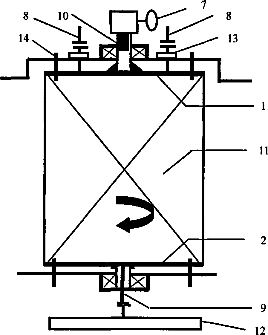
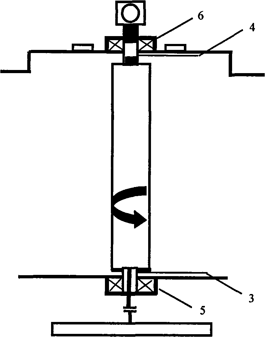
[0013] refer to figure 1 , figure 2 As shown, the two ends of the heat exchange surface are divided into a steam supply pipe 8 and a drain pipe 9. There are two steam supply pipes 8 on the steam supply side and one drain pipe 9 on the drain side. The drain pipe 9 on the drain side is located at the outlet header 2. In the middle position, the rotating shaft on the hydrophobic side is a round pipe (called "front rotating shaft 3"), and the drain pipe 9 passes through the front rotating shaft 3. One side of the front rotating shaft 3 is welded to the outlet header 2, and the other side is connected to the front bearing. 5 connection, which is an interference fit; on the steam supply side inlet header 1, select a position coaxial with the hydrophobic side rotation shaft to weld the rear shaft 4, and the other side of the rear shaft 4 is connected to the rear bearing 6, which is still an interference fit , the rear bearing 6 is connected with the actuator 7 through the solid sha...


PUM


Abstract

The invention discloses a rotational structure of a boiler rotary air heater, wherein the air heater is generally divided into a plurality of groups of heat-transfer surfaces, each group of the heat-transfer surfaces can rotate independently and respectively, or only one group can rotate independently and other groups of the heat-transfer surfaces remain stationary all the same. The rotational structure comprises headers of the heat-transfer surfaces of the air heater, a front rotating shaft, a back rotating shaft and corresponding front bearing and back bearing, an actuating mechanism and the like. The front and the back rotating shaft are round tubes and are hollow, and one side of each rotating shaft is welded on the headers at two sides of the heat-transfer surfaces of the air heater respectively, while the other side is connected with the bearings and in interference fit with the bearings. The other side of the connecting bearing of the back rotating shaft is selected to be connected with the driving actuating mechanism through a solid shaft. The rotational structure ensures that the air heater rotates freely and is convenient to mount, can rotate the air heater in the running process of a machine set, is applicable to air heaters arranged in any modes (a horizontal arrangement mode, a vertical arrangement mode or other arrangement modes), and has better universality.

Description

technical field [0001] The invention relates to a boiler rotary heater, in particular to a rotary structure of the boiler rotary heater. Background technique [0002] The boiler heater is a heat exchange device for preheating the cold air entering the air preheater. Large-scale power plant boilers are divided into a primary air heater and a secondary air heater. To prevent low temperature corrosion in the low temperature section of the air preheater. Except in the cold winter, the air heater does not need to be put into operation for most of the year. However, even if the air heater is not in operation, there will be resistance in the air duct due to the existence of the heat exchange surface of the air heater. Although there is a conception of a rotary heater, the actual operation of the rotation is relatively difficult, mainly because the arrangement of the steam supply pipe and the drain pipe on the heat exchange surface is relatively complicated. As mentioned above, t...

Claims


Application Information

Patent Timeline
IPC IPC(8): F23L15/00
CPCY02E20/34
Inventor 吴东垠
Owner IN LINAC ENERGY INNOVATION
Why Eureka
Try Eureka