
Combined sampling valve

A sampling valve and combined technology, applied in sampling devices, sliding valves, valve devices, etc., can solve problems such as increasing the initial construction cost of equipment

Inactive Publication Date: 2009-11-11
FUJIAN XINDA VALVE
View PDF0 Cites 4 Cited by
  • Summary
  • Abstract
  • Description
  • Claims
  • Application Information

AI Technical Summary

Problems solved by technology

[0002] Sampling valves are used in oil fields, oil refining plants and other fluid transportation occasions. The sampling valves are usually paired with pressure gauges. Specifically, on the pressure fluid transportation pipeline, not only the fluid pressure in the pipeline needs to be monitored, but also For fluid sampling and analysis, it is necessary to install a pressure gauge and a sampling valve on the fluid delivery pipeline at the same time. As a result, when the pressure gauge is damaged and needs to be replaced, there is still high-pressure fluid in the connection between the pressure gauge and the pipeline. During the process, the high-pressure fluid is sprayed out, which is not what the operator wants to see. At the same time, setting the sampling valve separately on the pipeline will increase the initial construction cost of the equipment

Method used


Image

  • Combined sampling valve
  • Combined sampling valve

Examples


Embodiment Construction

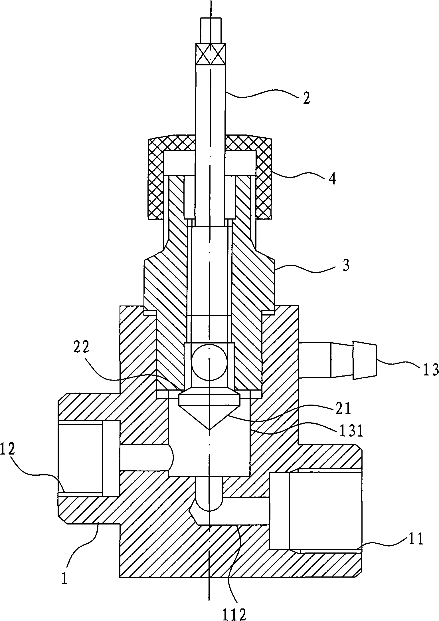
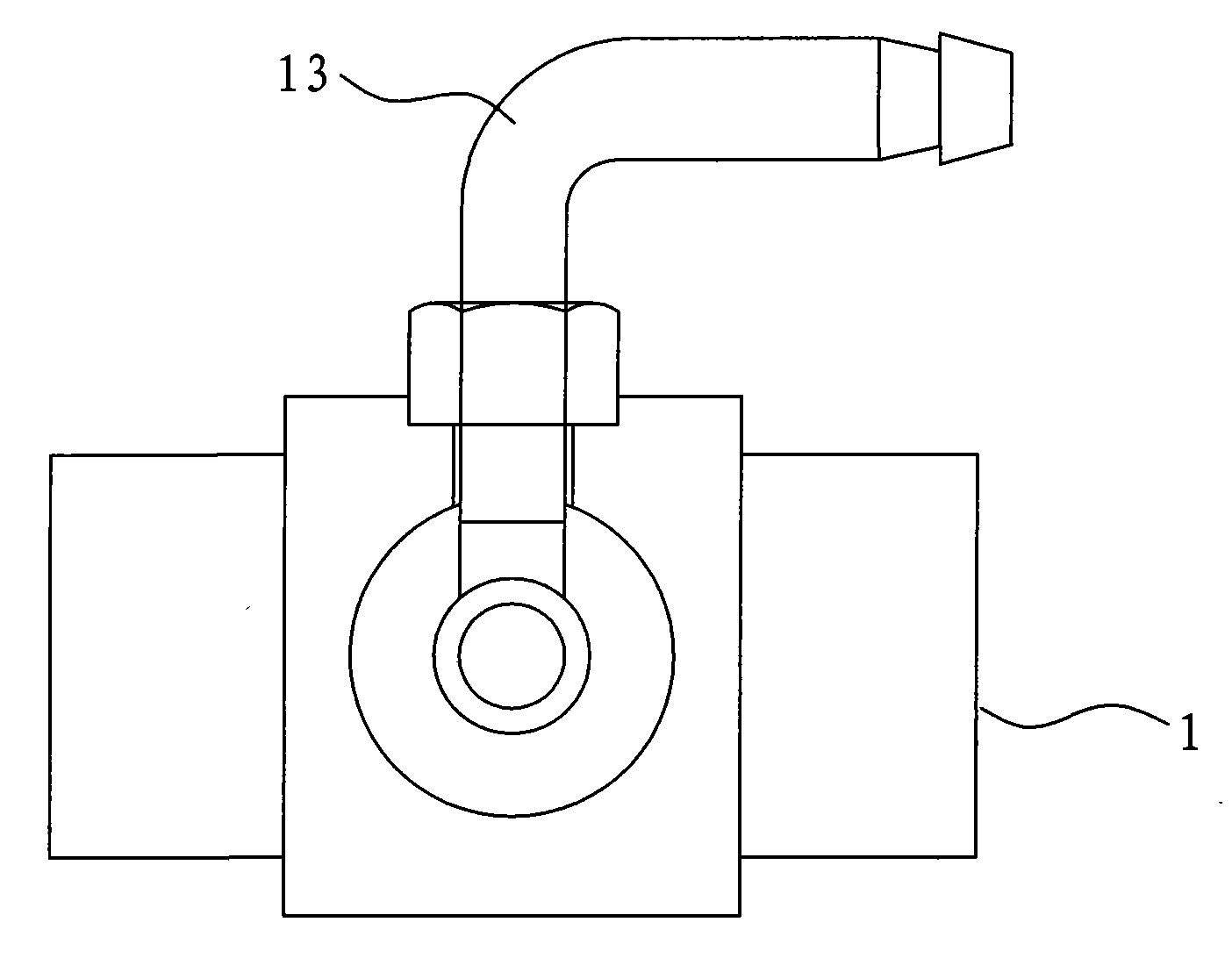
[0008] refer to figure 1 with figure 2 , the embodiment of the present invention discloses a kind of petroleum sampling valve that is used on the pipeline of oil field, and it comprises valve body 1, pressure gauge (not shown in the figure), valve stem 2, cock 3 and nut 4, and described valve The body 1 is provided with a liquid inlet 11, a liquid outlet 12 and a sampling port 13, and the liquid inlet 11 and the liquid outlet 12 are communicated through a liquid channel 112 arranged in the valve body 1, and the sampling port 13 It communicates with the middle part of the liquid channel 112 through the sampling channel 131 provided in the valve body 1, the cock 3 is screwed on the valve body 1, the valve stem 2 is screwed on the cock 3 through an external thread and one end is located outside the valve body 1, the valve There is a limit step on the stem 2, and the nut 4 is set on the cock 3 to prevent the valve stem 2 from falling off the valve body 1 through the limit step. ...


PUM


Abstract

The invention provides a combined sampling valve with simple structure and low cost, comprising a valve body, a pressure gauge and a valve rod, wherein the valve rod is provided with an inlet, an outlet and a sampling hole. The inlet and the outlet are communicated by a liquid passage arranged in the valve body, the sampling hole is communicated with the middle part of the liquid passage by a sampling passage arranged in the valve body, the valve rod is removably arranged on the valve body, one end of the valve rod extends to the sampling passage, wherein the valve rod is configured in a manner that the sampling passage is open and the liquid passage is ultimately closed when the valve rod shifts towards the liquid passage as well as that the liquid passage is open and the sampling passage is ultimately closed when the valve rod shifts far from the liquid passage, and the other end of the valve rod is arranged outside the valve rod and the pressure gauge is arranged on the outlet. The invention is used on a pressure fluid transportation pipeline.

Description

technical field [0001] The invention relates to a sampling valve, in particular to a combined sampling valve used on a pressure fluid pipeline. Background technique [0002] Sampling valves are used in oil fields, oil refining plants and other fluid transportation occasions. The sampling valves are usually paired with pressure gauges. Specifically, on the pressure fluid transportation pipeline, not only the fluid pressure in the pipeline needs to be monitored, but also For fluid sampling and analysis, it is necessary to install a pressure gauge and a sampling valve on the fluid delivery pipeline at the same time. As a result, when the pressure gauge is damaged and needs to be replaced, there is still high-pressure fluid in the connection between the pressure gauge and the pipeline. During the process, the high-pressure fluid is sprayed out, which is not what the operator wants to see. At the same time, setting the sampling valve separately on the pipeline will increase the i...

Claims


Application Information

Patent Timeline
IPC IPC(8): G01N1/20F16K3/18F16K37/00
Inventor 陈春生
Owner FUJIAN XINDA VALVE
Learn More