Printing method for realizing vignetting effectof automobile instrument dial

A technology of automobile instrumentation and printing method, applied in screen printing method, optics, instruments, etc., can solve the problems of not meeting the needs of automobile development, not producing halo effects, etc., achieving low cost, short time period, and adjusting data. flexible effects

Inactive Publication Date: 2009-11-11
SHANGHAI DELCO ELECTRONICS & INSTR
View PDF0 Cites 6 Cited by
  • Summary
  • Abstract
  • Description
  • Claims
  • Application Information

AI Technical Summary

Problems solved by technology

[0002] Each automobile manufacturer has different methods of processing the front effect of the instrument dial. For example, the dial spraying method and laser engraving method published on HC. Produces a halo effect, which cannot meet the needs of the development of this field of automobiles

Method used


Image

  • Printing method for realizing vignetting effectof automobile instrument dial

Examples


Embodiment 1

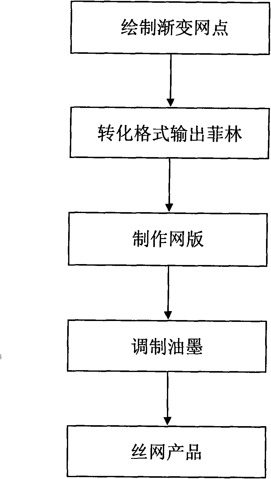
[0051] use as figure 1 Shown flow process, the halo printing method of the dial of the automobile instrument of the present invention comprises the following steps:

[0052] (1) Draw circular dots with gradient sizes in engineering drawing software:

[0053] (a) In the engineering drawing software AUTOCAD, first determine the position of the area where the halo effect of the dial is produced;

[0054] (b) In the software, the inner ring is drawn with circular uniformly distributed small dots. After several trial productions, it is determined that the minimum printing dot diameter for screen printing is 0.20mm;

[0055] (c) In the software, the distance between dots drawn on the same circle is 0.9mm, and the distance between adjacent inner and outer rings is 0.5mm;

[0056] (d) Based on the inner ring, the diameter of the dot increases by 0.4mm for each outer circle, and the circle dot design is completed;

[0057] (2) After converting it into a graphic design software forma...

Embodiment 2

[0073] use as figure 1 Shown flow process, the halo printing method of the dial of the automobile instrument of the present invention comprises the following steps:

[0074] (1) Draw circular dots with gradient sizes in engineering drawing software:

[0075] (a) In the engineering drawing software AUTOCAD, first determine the position of the area where the halo effect of the dial is produced;

[0076] (b) In the software, the inner ring is drawn with circular uniformly distributed small dots. After several trial productions, it is determined that the minimum printing dot diameter for screen printing is 0.25mm;

[0077] (c) In the software, the distance between dots drawn on the same circle is 1mm, and the distance between adjacent inner and outer circles is 0.6mm;

[0078] (d) Based on the inner ring, the diameter of the dot increases by 0.6mm for each outer circle, and the circle dot design is completed;

[0079] (2) After converting it into a graphic design software forma...


PUM

PropertyMeasurementUnit
diameteraaaaaaaaaa
diameteraaaaaaaaaa
diameteraaaaaaaaaa

Abstract

The invention provides a printing method for realizing the vignetting effect of an automobile instrument dial. The printing method comprises the following steps: (1) drawing annular dots with gradually changed sizes in engineering drawing software; (2) converting the drawing into graphic design software, arranging a plurality of crossing angular lines around Film and outputting the Film, wherein the angular lines are as thick as 0.2-0.35 mm; (3) producing a printing screen according to the Film; and (4) mixing printing ink for coloring, printing and then obtaining the automobile instrument dial with the vignetting effect. The vignetting effect of the automobile instrument dial is obtained by combining the engineering software drawing by a dot-printing technology in the screen printing process. By arranging the annular dots on the automobile instrument dial and under the co-effect of printing ink color mixing and inside instrument illumination, when the inside instrument illumination is started, the visual effect of gradual brightness change of an inner circle and an outer circle at a vignetting position can be achieved. The adoption of the printing method can simplify printing procedures and has the advantages of low cost, short time period, flexible product data adjustment, obvious effect, and the like.

Description

technical field [0001] The invention relates to a printing method for an automobile instrument dial, in particular to a printing method for producing a halo effect on the front of an automobile instrument dial. Background technique [0002] Various automobile manufacturers have different methods of processing the front effect of the instrument dial. For example, the dial spraying method and laser engraving method published on the HC website cannot produce a halo effect and cannot meet the needs of the development of this field of automobiles. Contents of the invention [0003] The technical problem to be solved by the present invention is to provide a printing method for the halo effect of the dial of an automobile instrument, so as to overcome the above-mentioned defects in the prior art and meet the development needs of related fields. [0004] Method of the present invention comprises the steps: [0005] (1) Draw ring-shaped dots with gradient sizes in engineering draw...

Claims


Application Information

Patent Timeline
Patent Type & Authority Applications(China)
IPC IPC(8): G03F5/00
Inventor 杨毅朱伟东刘翠绒
Owner SHANGHAI DELCO ELECTRONICS & INSTR
Why Eureka
Try Eureka