Low-outline ultra-wideband plow-shaped antenna

An ultra-broadband, low-profile technology, applied in the direction of slot antennas, radiating element structures, circuits, etc., can solve the problems of reducing the longitudinal profile of the antenna, the deterioration of the antenna performance, and the high profile of the plow-shaped antenna, so as to improve the directivity and improve the front-to-back ratio Effect

Inactive Publication Date: 2009-11-11
XIDIAN UNIV
View PDF0 Cites 4 Cited by
  • Summary
  • Abstract
  • Description
  • Claims
  • Application Information

AI Technical Summary

Problems solved by technology

[0003] The purpose of the present invention is to solve the problem of the high profile of the traditional plow antenna, and provide a low-profile ultra-wideband plow antenna to reduce the longitudinal profile of the antenna, avoid the deterioration of antenna performance, and meet the low-profile requirements of the ultra-wideband array

Method used


Image

  • Low-outline ultra-wideband plow-shaped antenna
  • Low-outline ultra-wideband plow-shaped antenna
  • Low-outline ultra-wideband plow-shaped antenna

Examples


Embodiment Construction

[0021] The structure and performance of the present invention will be described in detail below with reference to the accompanying drawings.

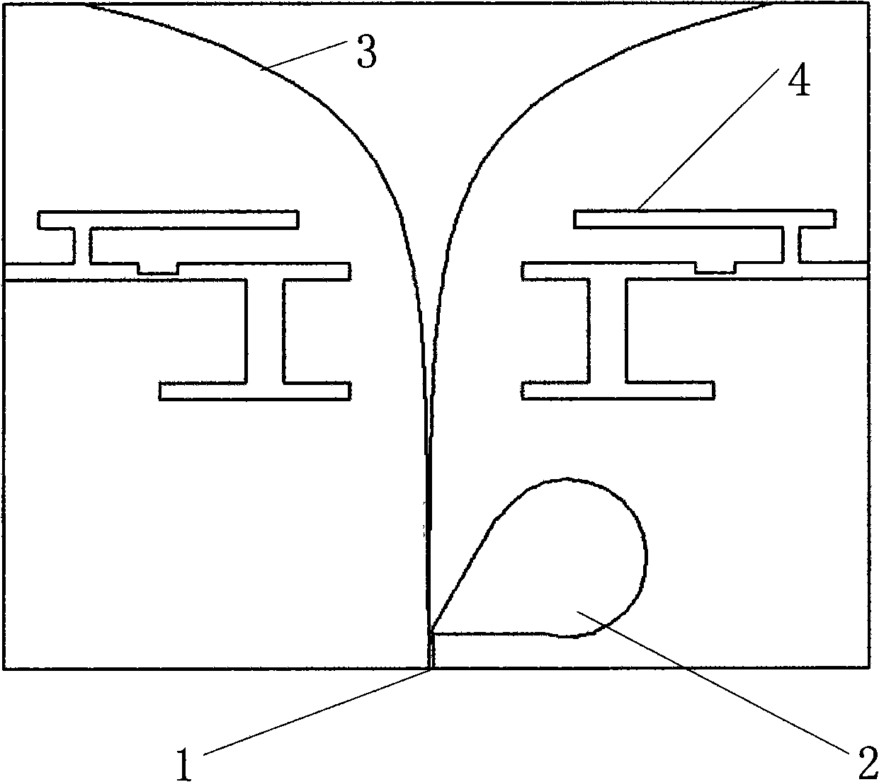
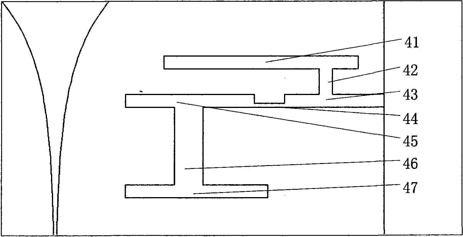
[0022] refer to figure 1 , the example given by the present invention is a low-profile plow antenna whose operating bandwidth is the upper limit frequency f H : lower limit frequency f L =4:1. The antenna is mainly composed of a single-sided copper-clad dielectric board. The copper-clad dielectric in this implementation case is made of FR4 material with a dielectric constant of 4.4 and a thickness of 1.5mm. The specific structure includes four parts: a coplanar waveguide impedance converter 1, an open circuit cavity 2, a left-right symmetrical exponential radiator 3 and a double "work"-shaped loading slot 4.

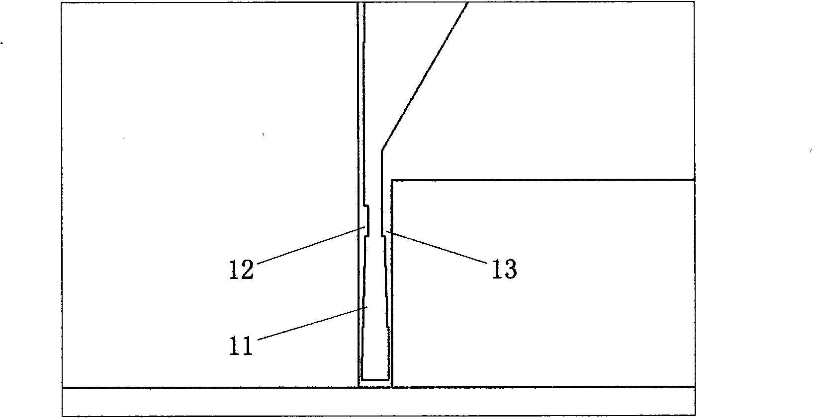
[0023] The structure of the coplanar waveguide impedance transformer 1 is as follows figure 2 As shown, it consists of a coplanar waveguide center strip 11, a left slot line 12 and a right slot line 13. The central conductiv...


PUM


Abstract

The invention discloses a low-outline ultra-wideband plow-shaped antenna, which consists of a dielectric substrate and a single-layer radiation copper layer coated on the dielectric substrate, wherein the copper layer comprises a coplanar waveguide impedance transformer (1), an open circuit cavity (2) and left-right symmetrical index-like radiators (3); a left trough line (12) of the coplanar waveguide impedance transformer (1) is connected with the index-like radiators (3) transitionally, a right trough line (13) is connected with the open circuit cavity (2), a central conduction band (11) is connected with the right-side index-like radiator, each index-like radiator (3) is provided with a dual I-shaped loading groove (4) which has an upper structure and a lower structure, and a lower transverse loading groove (43) of an upper I shape is connected with an upper transverse loading groove (45) of a lower I shape through a transverse narrow grooved wire (44); and the central conduction band (11) of the coplanar waveguide impedance transformer (1) has a rectangular stepped gradually changing structure. The low-outline ultra-wideband plow-shaped antenna has a simple structure, covers 4:1 bandwidth, has good directing property, and can be used in the field of ultra-wideband wireless communication.

Description

technical field [0001] The invention belongs to wireless communication antennas, in particular to a plow-shaped antenna, which is mainly used in ultra-wideband low-profile antenna arrays. technical background [0002] In order to achieve seamless global coverage in modern communications, high-speed multimedia communications of voice, text, image, and video can be performed simultaneously. The communication network should be a comprehensive network that combines wired and wireless technologies including multiple communication technologies. In this context, due to the ultra-wideband technology has a huge bandwidth, very low power, it can realize the reuse of existing frequency resources and other remarkable features. It brings a new way of voice and data communication without occupying the already crowded frequency resources. Achieving a very large bandwidth of the antenna is the first problem to be solved. Conventional radio communication is based on the traditional antenna...

Claims


Application Information

Patent Timeline
Patent Type & Authority Applications(China)
IPC IPC(8): H01Q1/36H01Q13/10
Inventor 张小苗吴青锋李晋阳应涛
Owner XIDIAN UNIV
Why Eureka
Try Eureka