Transmission power control method and transmission device

一种发送功率控制、发送装置的技术,应用在功率放大器、放大装置的零部件、电气元件等方向,能够解决发送功率的变动、输出功率不连续、易于变动等问题,达到提高精度的效果

Inactive Publication Date: 2009-11-11
PANASONIC CORP
View PDF0 Cites 0 Cited by
  • Summary
  • Abstract
  • Description
  • Claims
  • Application Information

AI Technical Summary

Problems solved by technology

[0007] like figure 2 As shown, the output power of uncompressed mode tends to fluctuate due to various reasons, so when switching between compressed mode and uncompressed mode, the possibility of output power discontinuity is high, resulting in a large transmission Possibility of power fluctuation is high

Method used


Image

  • Transmission power control method and transmission device
  • Transmission power control method and transmission device
  • Transmission power control method and transmission device

Examples


Embodiment approach 1

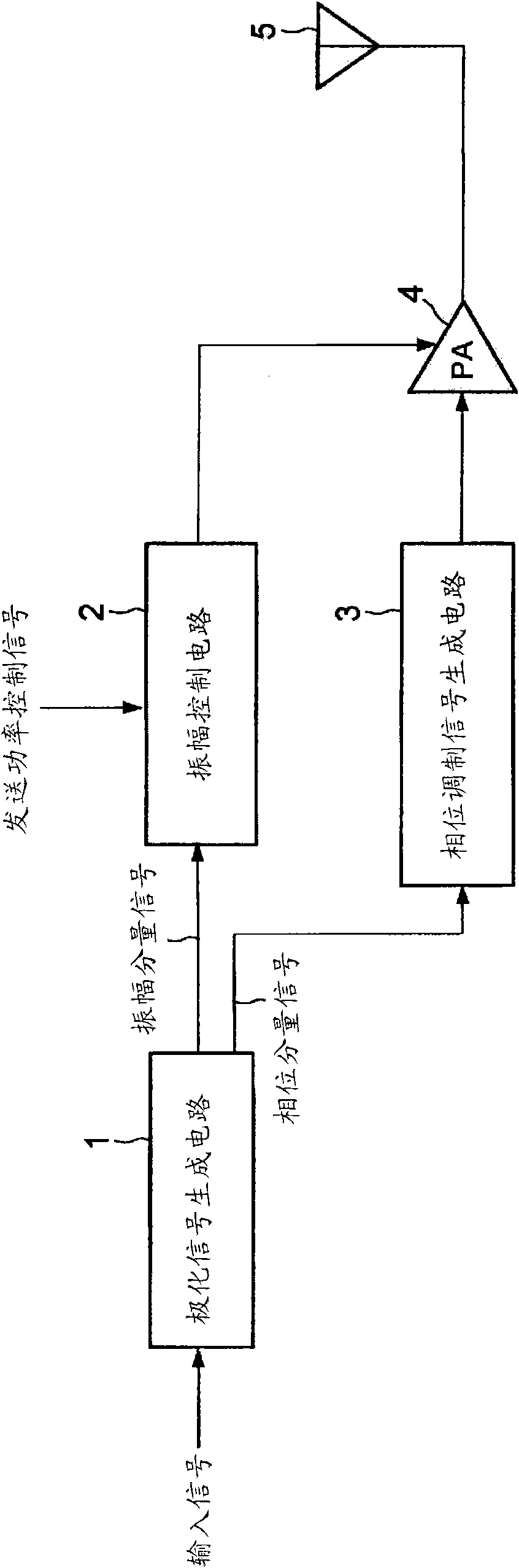
[0052] Figure 6 The configuration of the polar modulation transmission device according to the embodiment of the present invention is shown in . Figure 6 The polar modulation sending device 100 includes: a polar signal generation circuit 101, a phase modulation signal generation circuit 102, a power amplifier (PA) 103, an amplitude control circuit 104, a variable gain amplifier (VGA) and / or an attenuator. A variable amplification circuit 105 , and a power correction loop (alignment loop) 120 .

[0053] The power correction loop 120 includes a detection circuit 106 that detects the output power of the PA 103 , a low-pass filter (LPF) 108 , an analog-to-digital converter (ADC) 109 , and a transmission power control unit 107 .

[0054] The polarization signal generating circuit 101 generates an amplitude component signal and a phase component signal from an input signal. Specifically, polarized signal generating circuit 101 operates based on the input signal from spreading se...

Embodiment approach 2

[0110] The hardware structure and Figure 6 are the same, so descriptions are omitted.

[0111] Transmission power control section 107 sets transmission power control value ΔP=0 to forcibly perform mode switching before setting the symbol boundary of transmission power control value ΔP based on the transmission power control signal, and uses this to set transmission power control value ΔP The average value P before the symbol boundary of and before the mode switching cur , and the average value P before setting the symbol boundary of the transmission power control value ΔP and after mode switching tar , detect the variation of the output power of PA103 before and after mode switching, and set the transmission power control value ΔP, based on the transmission power control value ΔP and the variation, correct the target transmission power P tar_set .

[0112] Figure 11 This is another flowchart for explaining the operation of the polar modulation transmission device 100 whe...

Embodiment approach 3

[0126] in with Figure 6 Corresponding parts are denoted with the same reference numerals Figure 13 In , the configuration of the polar modulation transmission device 200 according to this embodiment is shown.

[0127] The polar modulation sending device 200 except Figure 6 In addition to the configuration of the polar modulation transmitting device 100, a spreading unit 210 and an averaging unit 220 are further included.

[0128] The spreading unit 210 spreads the input signal, and outputs the spread signal to the polarization signal generating circuit 101 . For example, in the case of generating an HSUPA signal, the spreading unit 210 multiplies the DPDCH signal, DPCCH signal, HS-DPCCH signal, and E-DPCCH signal by spreading codes Cd, Cc, Chs, Ced, and Cec respectively, and adjusts Beta ratio c(Bc), Beta ratio d(Bd), Beta ratio hs(Bhs), Beta ratio ed(Bed), and Beta ratio ec(Bec) as gain factors, thereby generating the HSUPA signal, and the generated The HSUPA signal is...


PUM


Abstract

Provided is a transmission power control method capable of accurately controlling a transmission power even when the transmission power control time is limited. The method includes: a first measurement step for measuring an output power of a power amplifier before mode switching during a symbol section preceding a symbol section for switching the power amplifier mode; a first setting step for setting a target power of the power amplifier after the mode switching according to the measurement result obtained in the first measurement step and a transmission power control signal; a second measurement step for measuring an output power of the power amplifier after the mode switching which is controlled by using the target power set by the first setting step, during the symbol section for switching the power amplifier mode; and a second setting step for setting a target power corrected according to the measurement result obtained by the second measurement step.

Description

technical field [0001] The present invention relates to a transmission power control method in a polar modulation transmission device. Background technique [0002] figure 1 An example of a typical transmission device using a polar modulation method is shown. The transmission device includes a polarization signal generation circuit 1 , an amplitude control circuit 2 , a phase modulation signal generation circuit 3 , and a power amplifier (hereinafter referred to as “PA”) 4 . In this transmission device, a polarization signal generation circuit 1 generates a signal related to the amplitude and phase of a transmission modulation signal from an input signal (that is, a transmission modulation signal). The amplitude control circuit 2 controls the power supply voltage supplied to PA4 based on the amplitude component signal, and the phase modulation signal generation circuit 3 generates a phase modulation signal input to PA4 based on the phase component signal. [0003] Actuall...

Claims


Application Information

Patent Timeline
Patent Type & Authority Applications(China)
IPC IPC(8): H03F3/24
CPCH04B2001/0416H03F3/245H03F2200/105H03F1/0205H03F2200/451
Inventor 松冈昭彦漆原伴哉加里·多韦恩·李
Owner PANASONIC CORP
Why Eureka
Try Eureka