
Heat insulation device for U-shaped pipe laying heat exchanger

A heat insulation device and heat exchanger technology, which is applied in the direction of heat insulation protection pipelines, heat pumps, pipeline protection, etc., can solve the problems of increased thermal short circuit loss, affecting refilling grouting materials, and increasing the number of U-shaped pipes, etc., to achieve The effect of heat exchange improvement

Inactive Publication Date: 2012-06-27
NINGBO UNIV
View PDF4 Cites 0 Cited by
  • Summary
  • Abstract
  • Description
  • Claims
  • Application Information

AI Technical Summary

Problems solved by technology

For this reason, in order to increase the heat transfer between the U-shaped pipe and the soil, it is necessary to use a recharge material with a thermal conductivity greater than that of the soil (generally, the thermal conductivity of the soil is between 0.8 and 1.6W / (m·K), and the recharge material The thermal conductivity should be greater than 1.8W / (m K)), and the larger the better within a certain range; in this way, the thermal short circuit loss between the two tubes will inevitably increase accordingly
Therefore, the above characteristics affect the use of refilling grouting materials to a certain extent, and directly lead to an increase in the number of U-shaped pipes and an increase in project cost

Method used


Image

  • Heat insulation device for U-shaped pipe laying heat exchanger
  • Heat insulation device for U-shaped pipe laying heat exchanger
  • Heat insulation device for U-shaped pipe laying heat exchanger

Examples


Embodiment 1

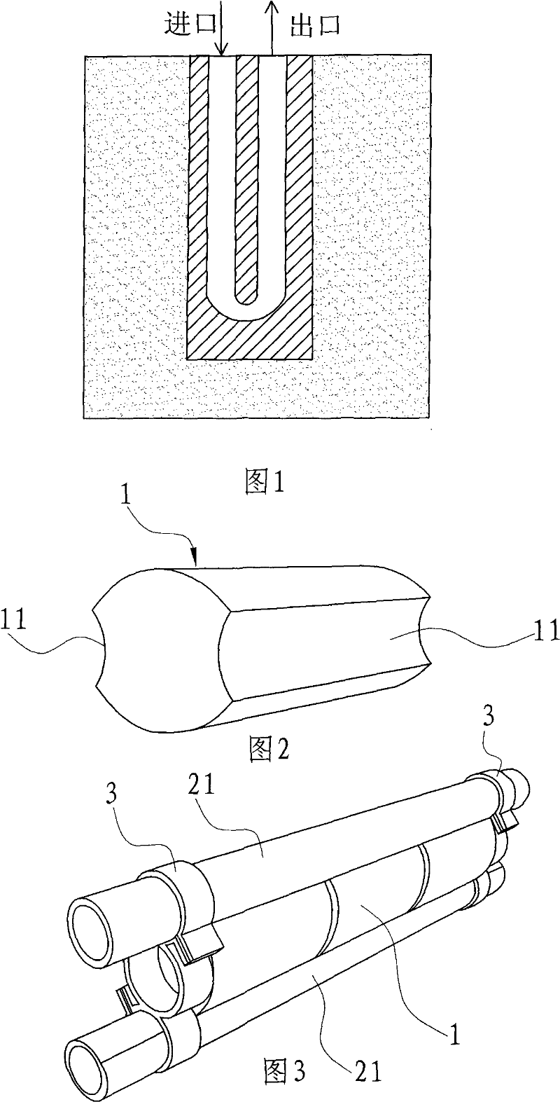
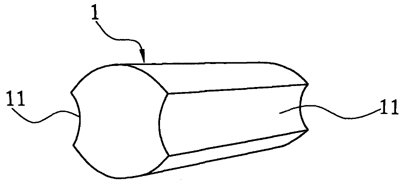
[0025] see figure 2 , 3 The heat insulation device of the U-shaped borehole heat exchanger provided by the present invention includes a body 1, and the outer wall of the body 1 is axially symmetrically provided with a straight pipe section 21 of the single U-shaped heat exchange tube of the heat exchanger. The arc-shaped groove 11, and the body 1 is made of a material with a thermal conductivity within 0.02W / (m·K)~0.06W / (m·K) and a water absorption within 0.05~0.1%.

[0026] Here, the body 1 is generally cylindrical, and the diameter of the body 1 is slightly larger than the diameter of the straight pipe section 21 of the single U-shaped heat exchange tube of the heater.

[0027] During assembly, the heat insulating device and the single U-shaped heat exchange tube of the heat exchanger can be fastened with the fixing frame 3 .

Embodiment 2

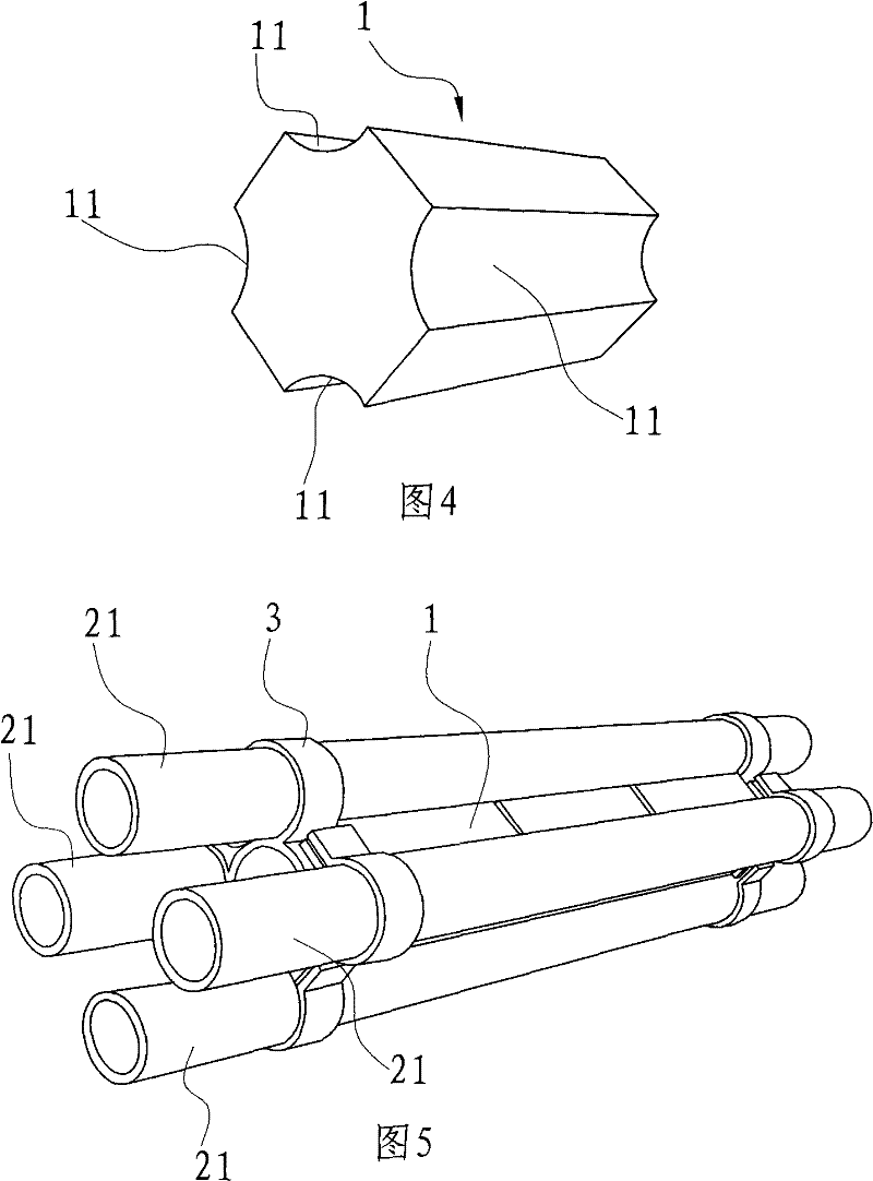
[0029] Different from the first embodiment, there are four arc-shaped grooves on the outer wall of the main body, which are arranged in a symmetrical structure. The heat insulation device of this structure is suitable for double U-shaped heat exchange tubes.

[0030] The main body 1 is generally column-shaped, and four arc-shaped grooves 11 are respectively arranged on the four corners of the column, and are fitted with the straight pipe sections 21 of the double U-shaped heat exchange tubes.


PUM


Abstract

The invention relates to a heat insulation device for a U-shaped pipe laying heat exchanger, which is arranged between straight tube sections of the U-shaped heat exchange pipes of the heat exchanger.The heat insulation device comprises a body, wherein an arc groove attached to the straight pipe sections of the U-shaped heat exchange pipe of the heat exchanger is axially arranged on the externalwall of the body; and the body is made of a material with the coefficient of heat conductivity of between 0.02-0.06W / (m-K). Compared with the prior art, the heat insulation device has the advantages that the heat interference phenomenon generated among the straight pipe sections of the U-shaped heat exchange pipe can be avoided through setting the heat insulation device with the coefficient of heat conductivity of between 0.02-0.06W / (m-K) among the straight pipe sections of the U-shaped heat exchange pipe of the heat exchanger, on the premise that the effective heat exchange area of the U-shaped pipe is not reduced, through ensuring the distance between two pipes of the U-shaped pipe and applying a high thermoresistance recharge material, the amount of heat exchange of the U-shaped pipe isimproved by about 15 percent.

Description

technical field [0001] The invention relates to a heat insulation device for a U-shaped buried tube heat exchanger. Background technique [0002] At present, the ground source (soil source) heat pump system used in our country adopts the mode of heat exchange between the medium flowing through the buried pipe and the earth (soil, stratum, groundwater). This heat exchanger is available in both vertical and horizontal borehole types. Technically horizontal and vertical buried pipe systems are basically the same. The horizontal buried pipe is buried in shallow soil, and the setting is relatively simple. However, it occupies a large area, and the geothermal heat exchanger with horizontally buried pipes is affected by surface climate changes, and its efficiency is low. Therefore, the application of the ground source heat pump air-conditioning system of the horizontal buried pipe type is restricted to a certain extent in the case of a large number of people and a small amount o...

Claims


Application Information

Patent Timeline
Patent Type & Authority Patents(China)
IPC IPC(8): F16L59/02F25B30/06
Inventor 闫成文
Owner NINGBO UNIV
Learn More