Fore/aft looking airborne radar

An airborne radar, aircraft technology, applied in specific array feeding systems, modular arrays, antennas suitable for movable objects, etc., can solve problems such as high cost, cumbersomeness, hinder the installation of sensors, etc., to achieve easy implementation. , low cost, good lobe width and sweepability

Inactive Publication Date: 2009-11-18
TELEFON AB LM ERICSSON (PUBL)
View PDF1 Cites 7 Cited by
  • Summary
  • Abstract
  • Description
  • Claims
  • Application Information

AI Technical Summary

Problems solved by technology

The solution of equipping an additional radar system with these antennas has the disadvantage of high cost
[0005] Alternatively, the forward and rear looking antennas connected to normal radar have the disadvantage that long high power RF feed lines must be pulled from the radar to the forward / rear looking antennas
This solution becomes unnecessarily bulky, and it hinders the possibility of installing other important sensors in the radome at the front end

Method used


Image

  • Fore/aft looking airborne radar
  • Fore/aft looking airborne radar
  • Fore/aft looking airborne radar

Examples


Embodiment Construction

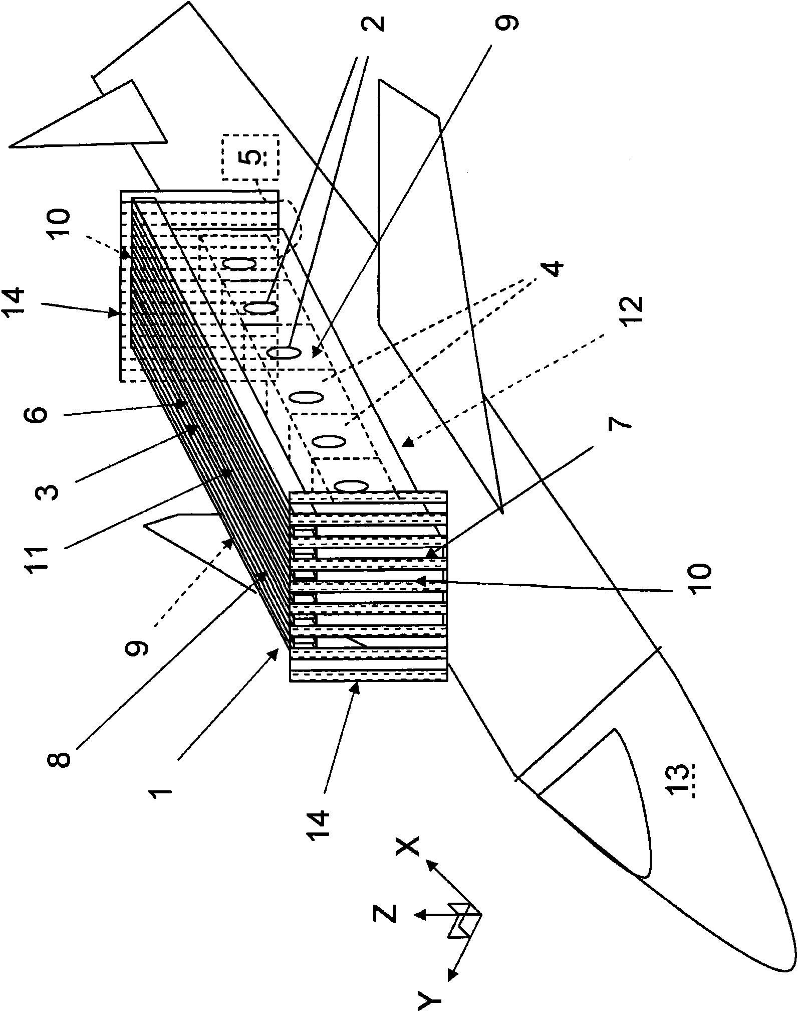
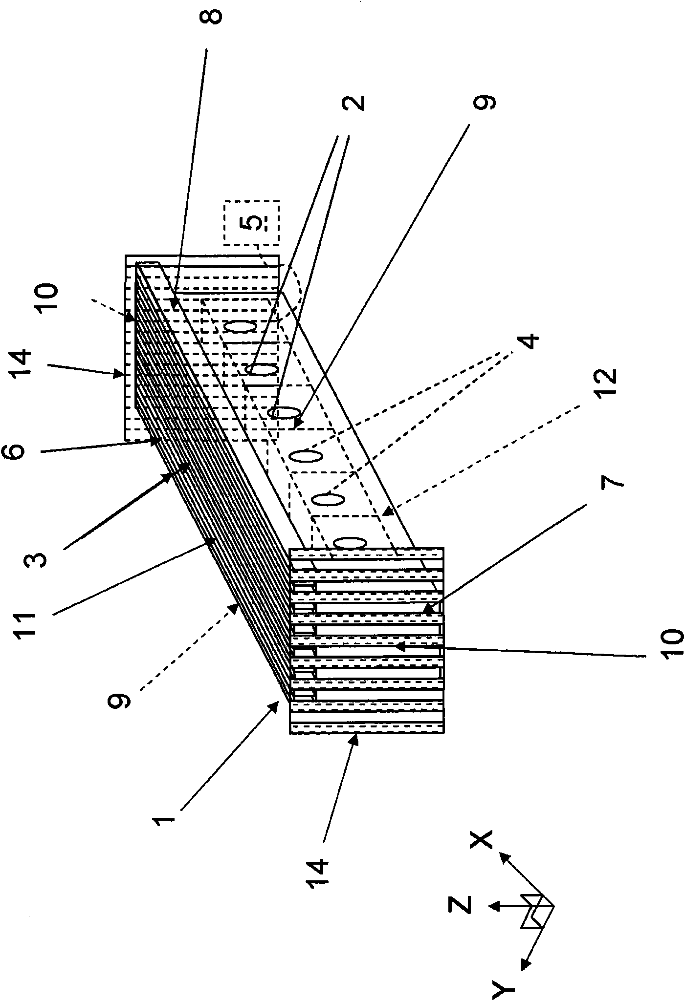
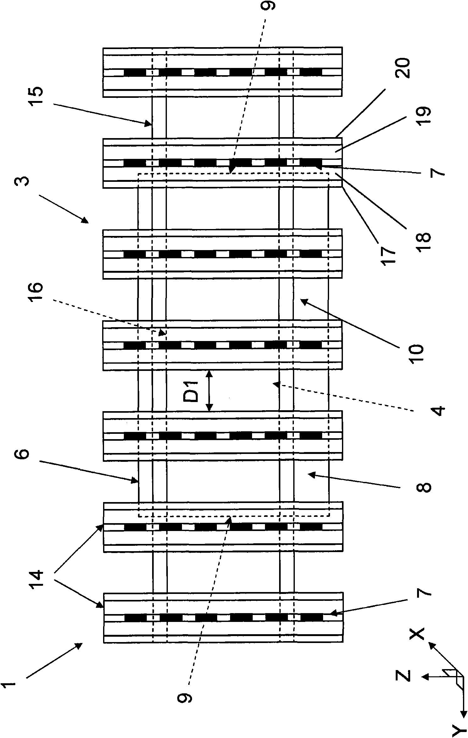
[0037] figure 1 An antenna system 1 for an airborne radar system according to the invention is shown schematically. The antenna system 1 comprises a plurality of first antenna elements 2 and a microwave power distribution system 3 comprising a plurality of first T / R units 4 arranged to transfer microwave power to and from a microwave receiver and generator 5 Assigned to the first antenna element 2. figure 1 An advantageous embodiment of a microwave power distribution system 3 is schematically taught. exist figure 1 , the power distribution system 3 comprises a planar assembly 6 of polarized first waveguides coupled to a plurality of second antenna elements 7 directed at an angle substantially perpendicular to the plurality of first antenna elements 2 . The first T / R unit 4 is arranged for distributing microwave energy to the first and second antenna elements 2,7.

[0038] The antenna system comprises a spine unit 8, which has two opposite long sides 9 extending along the h...


PUM


Abstract

The invention refers to an antenna system (1) for an airborne radar system. The antenna system (1) comprises a dorsal unit (8) having two opposing long sides (9) extending in a height direction (Z) and a longitudinal direction (X), and two opposing short sides (10) extending in a lateral direction (Y) and the height direction (Z), and an upper side (11) opposing a bottom side (12) each extending in the longitudinal direction (X) and the lateral direction (Y). The antenna system (1) comprises antenna devices (14) being interspaced and mounted in connection to one of the short sides or both the short sides (10) and extending in the height direction (Z). Each of the antenna devices (8) comprises a waveguide board (21).

Description

technical field [0001] The invention relates to an antenna system for an airborne radar system. The antenna system comprises a dorsal unit having two opposite long sides (long sides) extending along a height direction and a longitudinal direction, and two opposite short sides (short sides) extending along a transverse direction and a height direction, and an upper side opposite to the bottom side, each side expanding in the longitudinal direction and the transverse direction. The antenna system includes an antenna arrangement. Background technique [0002] In the field of radar devices for aircraft it is known to use a spine unit which is positioned on the fuselage of the aircraft and extends in the longitudinal direction of the aircraft, ie in the direction from the front to the rear. The spine unit includes a plurality of side-looking antenna elements positioned along the longitudinal direction of the spine unit for side-looking purposes. One problem with spine units is...

Claims


Application Information

Patent Timeline
Patent Type & Authority Applications(China)
IPC IPC(8): H01Q21/00H01Q3/26
CPCH01Q21/005H01Q21/0025H01Q3/26H01Q1/28
Inventor A·胡克
Owner TELEFON AB LM ERICSSON (PUBL)
Why Eureka
Try Eureka