
Double handle hand riveter

A kind of riveting gun and handle-type technology, which is applied in the field of double-handle riveting guns, can solve the problems of lengthening, increased production cost, labor-intensive use, etc., and achieve the effects of reducing the overall volume, simple and reasonable structure, and avoiding conflicts

Inactive Publication Date: 2009-11-25
袁建明
View PDF1 Cites 20 Cited by
  • Summary
  • Abstract
  • Description
  • Claims
  • Application Information

AI Technical Summary

Problems solved by technology

[0006] However, the prior art has the following defects: since the fixed block suit is fixed on the lower part of the pull rod, a perforation suitable for the pull rod must be provided on the fixed block, the thickness of the fixed block must be matched with the connecting rod, and one end of the pull rod must be To prepare the thread, the inner layer of the thread must also be equipped with a back hole for the rivet to pass through. Therefore, the manufacturing process of the tie rod and the fixing block is relatively complicated, resulting in high cost
According to the principle of leverage, the farther the distance between the two screws is, the length of the handle as the force arm must be lengthened, otherwise it will be very laborious to use
The lengthening of the handle will inevitably increase the volume of the riveting gun, resulting in an increase in production costs, and it is not easy to pack, transport and carry

Method used


Image

  • Double handle hand riveter
  • Double handle hand riveter
  • Double handle hand riveter

Examples


Embodiment 1

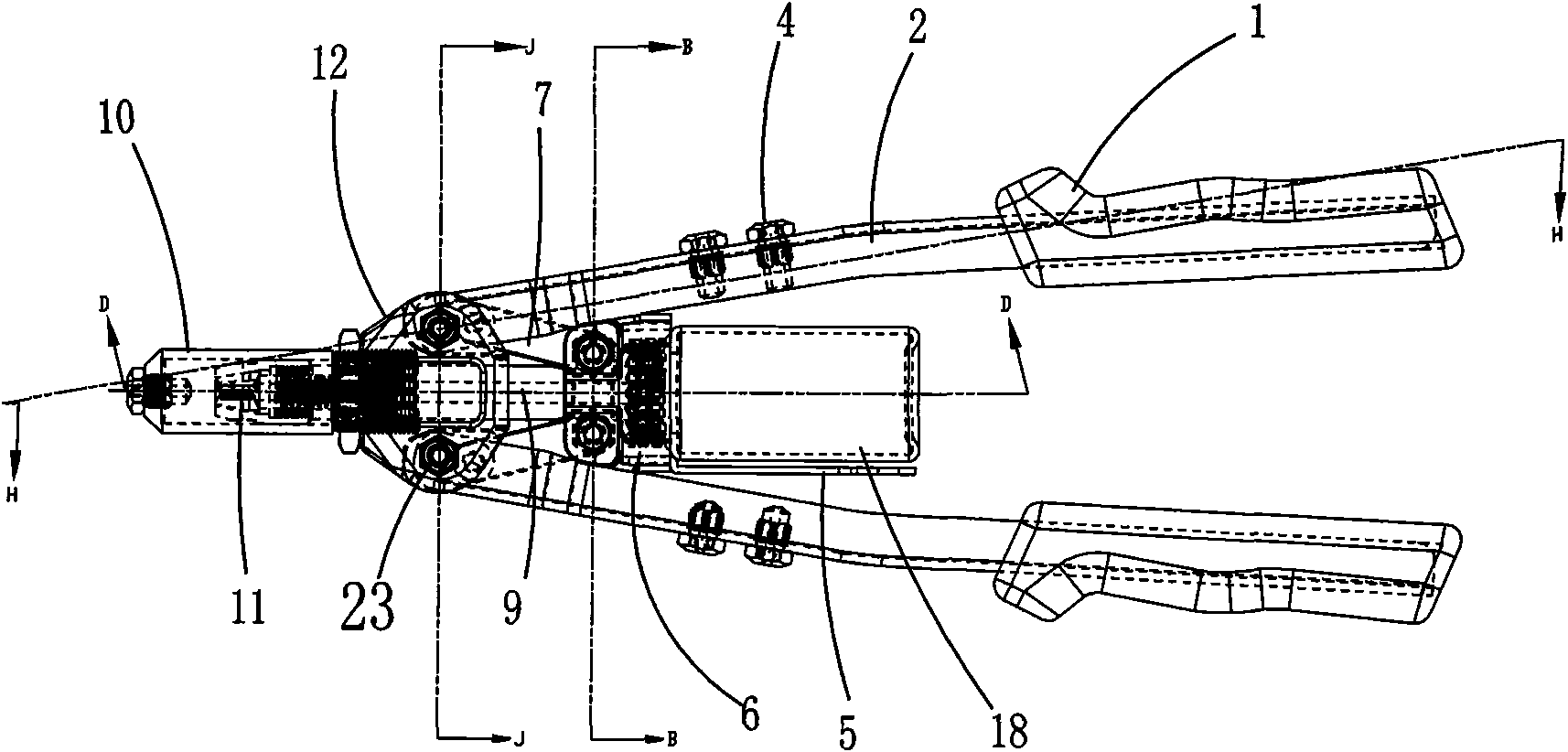
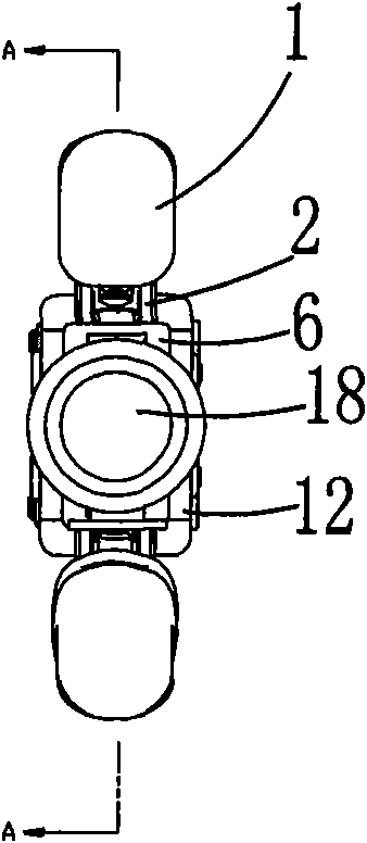
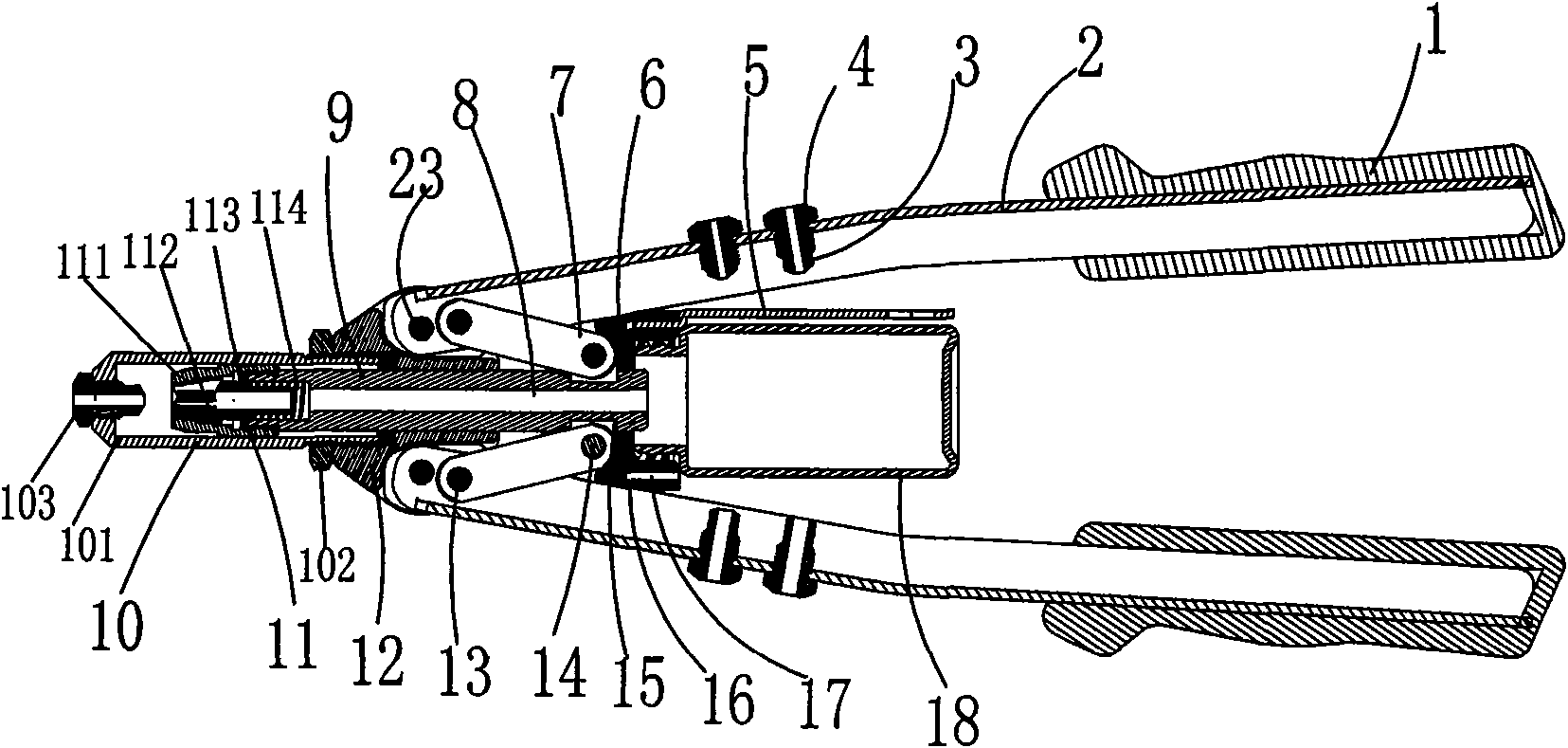
[0034] Such as Figure 1 to Figure 7As shown, a double-handled riveting gun includes a riveting gun base 12, an adjusting sleeve 101, an adjusting nut 102, and a guide nozzle 103 of the adjusting mechanism 10 arranged at the front end of the riveting gun base 12 are installed on the The catch seat 111, catch 112, ejector rod 113 and spring 114 of the blind rivet grip mechanism 11 in the adjustment mechanism 10, one end is respectively hinged with the two sides of the rivet gun seat 12 through the first screw shaft 23 The two handles 2 are movably inserted into the pull rod 9 in the center hole 20 of the rivet holder 12; it is characterized in that: the tail end of the pull rod 9 is provided with a fixing groove 21, and the fixing groove 21 The bottom surface is four planes, and every two adjacent planes are perpendicular to each other; in a pair of opposite surfaces of the fixing groove 21, two parallel to each other and compatible with the connecting rod 7 are embedded. Fixe...

Embodiment 2

[0041] Of course, the structure of the fixing groove 21 in the present invention can also adopt other structures besides the case of this embodiment. For example, the fixing groove 21 is an annular structure compatible with the fixing piece 15, which can also achieve the effects of easy manufacture, low cost, and firm and reliable use. The structure of embodiment 2 is basically the same as that of embodiment 1, the only difference between the two is that the fixing groove 21 provided at the tail end of the pull rod 9 is an annular groove (the figure of embodiment 2 is omitted). It is convenient to offer the annular groove processing, but it is very convenient and firm to be connected with the connecting rod 7 after the fixed piece 15 is installed.

Embodiment 3

[0043] Such as Figure 8 Shown, embodiment 3 product structure is close to embodiment 1,2.

[0044] Embodiment 3 is: a double-handled riveting gun, including a riveting gun base 12, an adjustment mechanism 10 arranged at the front end of the riveting gun base 12, one end of which is respectively connected to the riveting gun base through a first screw shaft 23 The two handles 2 hinged on both sides of 12 are movably inserted into the pull rod 9 in the central hole 20 of the rivet holder 12; it is characterized in that: the tail end of the pull rod 9 is provided with a fixing groove 21, The fixed slot 21 is embedded with a fixed piece 15 adapted thereto, and the left and right sides of the fixed piece 15 are connected to the handle 2 through the left and right connecting rods 7 respectively. 1. One end of the right connecting rod 7 is hinged to the fixed piece 15 through the second screw shaft 14, and the other end is hinged to the handle 2; the two sides of the riveting gun s...


PUM


Abstract

The invention discloses a double handle hand riveter comprising a riveter base, a regulating mechanism, a riveter holding mechanism, one end of which is hinged with two handles on both sides of the riveter base and a tie bar in a central hole of the riveter base, characterized in that rear end of the tie bar is provided with a fixed groove embedded with a fixed piece, both sides of which are respectively connected with the handles via a connecting rod; one end of the collecting rod is connected with the fixed piece via a second screw shaft and the other end is hinged with the handle. Handle matching grooves are arranged on both sides of the base. The handles are respectively hinged with the riveter base via a first screw shaft in the handle matching groove. The connecting rod is hinged with the handle via a pin rod. The hand riveter can be handle screw by replacing riveter holding mechanism with a screw holding mechanism. Manufacturing process of the fixed groove, the tie bar and the fixed piece on the tie bar is simple and reduces cost. Due to rational connection among the collecting rod, the handle and the riveter base, volume of the invention is reduced.

Description

technical field [0001] The invention relates to a riveting gun, in particular to a double handle riveting gun. Background technique [0002] Rivet guns can be divided into rivet guns and rivet nut guns. Generally speaking, the rivet gun uses the core pulling rivet for riveting; the rivet nut gun uses the rivet nut for riveting. [0003] Core-pulling rivets are a kind of rivets for single-sided riveting. This kind of rivets are especially suitable for riveting occasions where it is inconvenient to use ordinary rivets. Therefore, they are widely used in construction, automobiles, ships, aircraft, machines, electrical appliances, furniture and other products. . Among them, the open type oblate head core pulling rivets are the most widely used, the countersunk head core pulling rivets are suitable for riveting occasions where the surface needs to be smooth, and the closed type core pulling rivets are suitable for riveting occasions requiring higher load and certain sealing per...

Claims


Application Information

Patent Timeline
Patent Type & Authority Applications(China)
IPC IPC(8): B21J15/38
CPCB21J15/386
Inventor 袁建明
Owner 袁建明
Learn More