In-vehicle illuminating device

A technology for lighting devices and vehicles, which is applied to vehicle interior lighting devices, lighting devices, fixed lighting devices, etc., can solve the problem of fluorescent lamps entering the field of view of passengers, and achieve the effect of improving performance effects.

Inactive Publication Date: 2009-11-25
HONDA ACCESS CORP
View PDF1 Cites 2 Cited by
  • Summary
  • Abstract
  • Description
  • Claims
  • Application Information

AI Technical Summary

Problems solved by technology

[0004] However, in the above-mentioned Patent Document 1, although the light is irradiated in such a manner as to avoid the occupant sitting in the seat, part of the light is directly radiated into the...

Method used


Image

  • In-vehicle illuminating device
  • In-vehicle illuminating device
  • In-vehicle illuminating device

Examples


Embodiment Construction

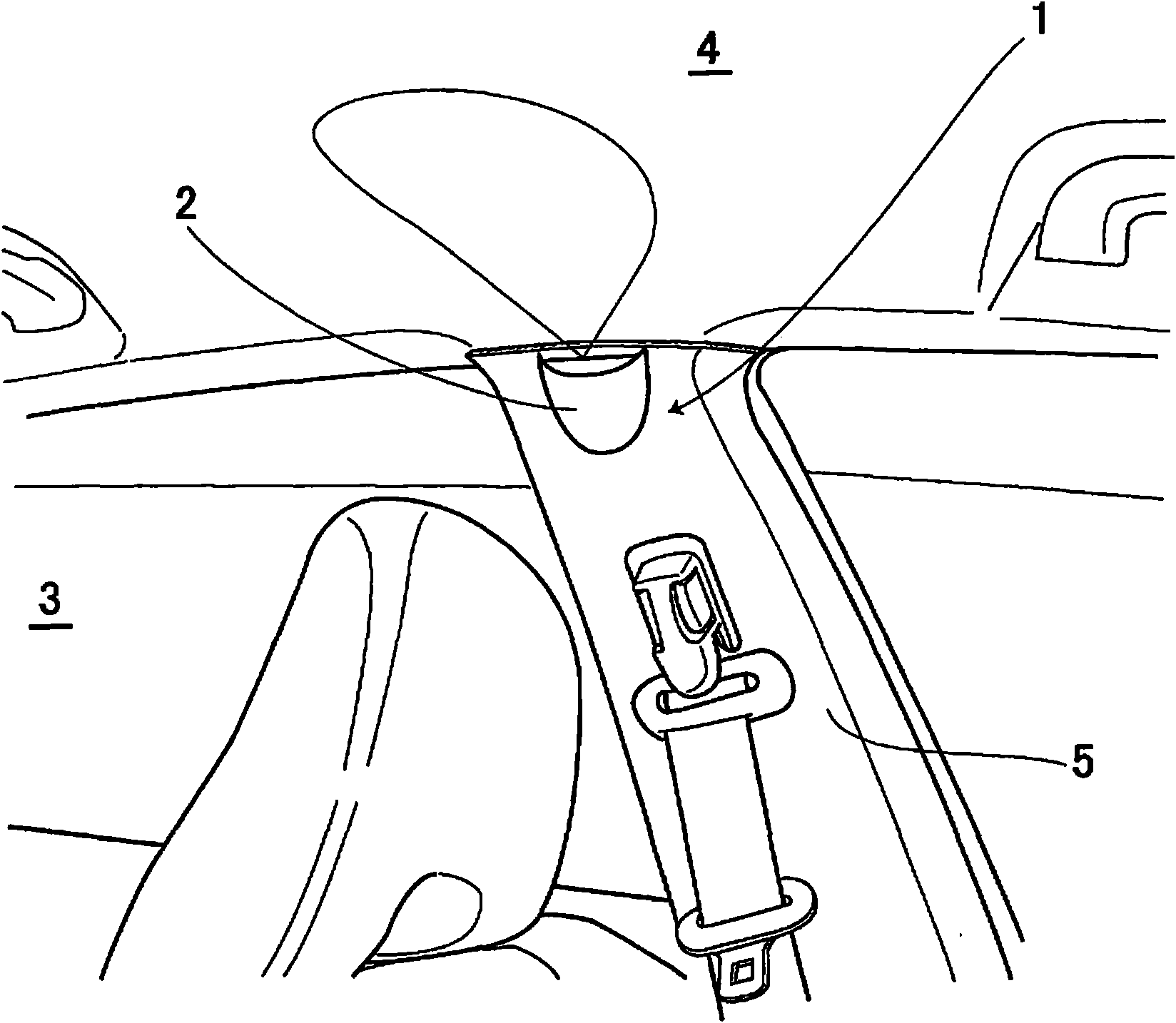
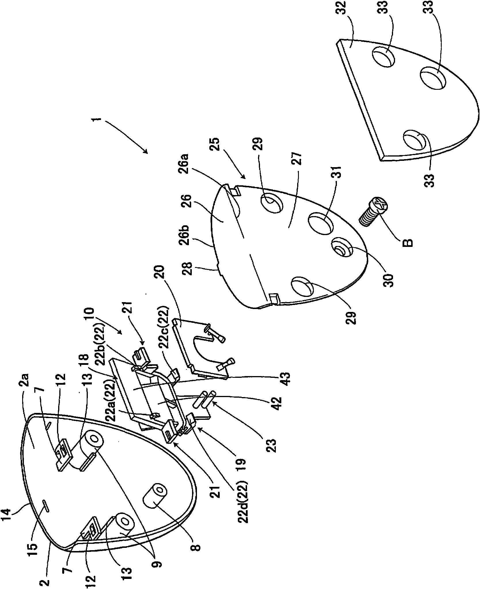
[0019] The best mode for carrying out the present invention will be described below with reference to the drawings. figure 1 The illustrated vehicle lighting device 1 includes a housing 2 and a light source unit described later built in the housing 2. The vehicle lighting device 1 is fixed to a pillar portion 5 of a vehicle interior 3 and can direct reflected light toward The ceiling 4 of the compartment 3 is illuminated. The housing 2 is made of plastic, such as polypropylene, and has an inverted triangle shape. The outer edge is gently curved from the front side to the back side, and an opening is formed at the upper end. Here, the pillar portion 5 refers to a pillar supporting both ends of a window provided on the side of the vehicle.

[0020] As a result, the vehicle lighting device 1 is formed in a thin flat plate shape, irradiates reflected light toward the ceiling 4 of the vehicle compartment 3 , and can illuminate the vehicle compartment 3 over a wide range.

[0021]...


PUM


Abstract

An in-vehicle illuminating device capable of preventing light emitted from a light source from coming directly into a passenger's sight. An in-vehicle illuminating device 1 includes a housing 2, a reflective member 18 provided within the housing 2, a light source or LEDs 10 orienting a light axis of light emitted therefrom to the reflective member 18. Reflected light obtained by allowing the reflective member 18 to reflect the light emitted from the LEDs 40 is irradiated to the outside of the housing 2, thus preventing light emitted from the LEDs 40 from coming directly into a passenger's sight.

Description

technical field [0001] The present invention relates to a lighting device for a vehicle, and is particularly suitable for a lighting device for a vehicle installed on a pillar portion or the like of a vehicle interior. Background technique [0002] Conventionally, an interior lighting device has been disclosed as a lighting device for a vehicle installed on a pillar portion of a vehicle compartment, for example, including a housing and a fluorescent lamp installed in the housing. A transmissive window that radiates in a parallel direction and a transmissive window that radiates light downward, and a reflector is formed between the inner end and the outer end of the transmissive window, and the reflector guides the light beam emitted from the fluorescent lamp to the above transmissive window (eg, Patent Document 1). Therefore, in the above-mentioned Patent Document 1, the light emitted from the fluorescent lamp is transmitted in two vertical directions, the first light is ra...

Claims


Application Information

Patent Timeline
IPC IPC(8): F21S8/10F21V7/04B60Q3/02F21W101/08F21Y101/02F21W106/00
CPCB60Q3/008B60Q3/0279B60Q3/74B60Q3/68B60Q3/20
Inventor 岩井史郎川村朋贵村林大和
Owner HONDA ACCESS CORP
Why Eureka
Try Eureka