
Liquid crystal display device
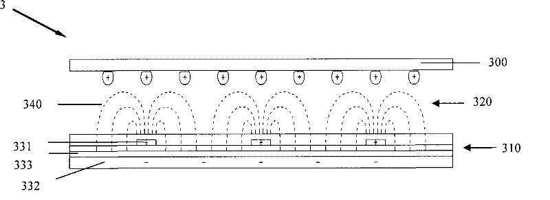
A liquid crystal display device and thin film transistor technology, which is applied to instruments, semiconductor devices, optics, etc., can solve the problem that the third liquid crystal display device 3 cannot achieve electrical neutrality, etc., and achieves the effect of solving image sticking and avoiding inaccurate compensation.
- Summary
- Abstract
- Description
- Claims
- Application Information
AI Technical Summary
Problems solved by technology
Method used
Image

Examples
no. 1 example
[0052] See Figure 5 , And refer to Image 6 , The first liquid crystal display device 1 in FFS (Fringe field switch) mode includes an upper substrate 100, a lower substrate 110 facing the upper substrate 100, and a lower substrate 110 sandwiched between the upper substrate 100 and the lower substrate 110 The liquid crystal layer 120. A number of data lines 111 and gate lines 112 perpendicular to each other are arranged on the lower substrate 110 of the first liquid crystal display device 1. The data line 111 and the gate line 112 define a number of pixel regions 113.
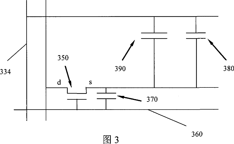
[0053] See Figure 7 , And refer to Figure 5 versus Picture 9 ,among them, Picture 9 It is a schematic diagram of an equivalent circuit of the first liquid crystal display device 1 in the FFS mode. A comb-shaped first pixel electrode 114 is formed in each pixel area 113 of the lower substrate 110. The comb-shaped first pixel electrode 114 is electrically connected to the first thin film transistor 130. The c...
no. 2 example
[0059] Refer below Picture 9 , Picture 10 and Picture 11 The second embodiment of the present invention will be described. The second embodiment is different from the first embodiment in that the liquid crystal display device of the second embodiment is an IPS mode liquid crystal display device. The same parts as in the first embodiment use the same reference numerals, and will not be repeated here.
[0060] See Picture 10 , And refer to Picture 11 The second liquid crystal display device 2 in IPS (In Plane Switching) mode includes an upper substrate 100, a lower substrate 110 facing the upper substrate 100, and a lower substrate 110 sandwiched between the upper substrate 100 and the lower substrate 110. The liquid crystal layer 120. A number of data lines 111 and gate lines 112 perpendicular to each other are arranged on the lower substrate 110 of the liquid crystal display device 2. The data line 111 and the gate line 112 define a number of pixel regions 113.
[0061] P...
PUM
 Abstract
Description
Claims
Application Information