Device for separating printing plates

A technology of printing plates and driving devices, which is applied in the field of printing plate devices, can solve the problems of structural consumption and inability to adapt the mode of action, and achieve the effect of great flexibility

Inactive Publication Date: 2009-12-02
HEIDELBERGER DRUCKMASHINEN AG
View PDF1 Cites 1 Cited by
  • Summary
  • Abstract
  • Description
  • Claims
  • Application Information

AI Technical Summary

Problems solved by technology

[0006]The devices known from the prior art are on the one hand extremely complex in structure and cannot be adapted to printing plates of different sizes in their mode of operation and must always be adapted to Largest possible plate size

Method used


Image

  • Device for separating printing plates
  • Device for separating printing plates
  • Device for separating printing plates

Examples


Embodiment Construction

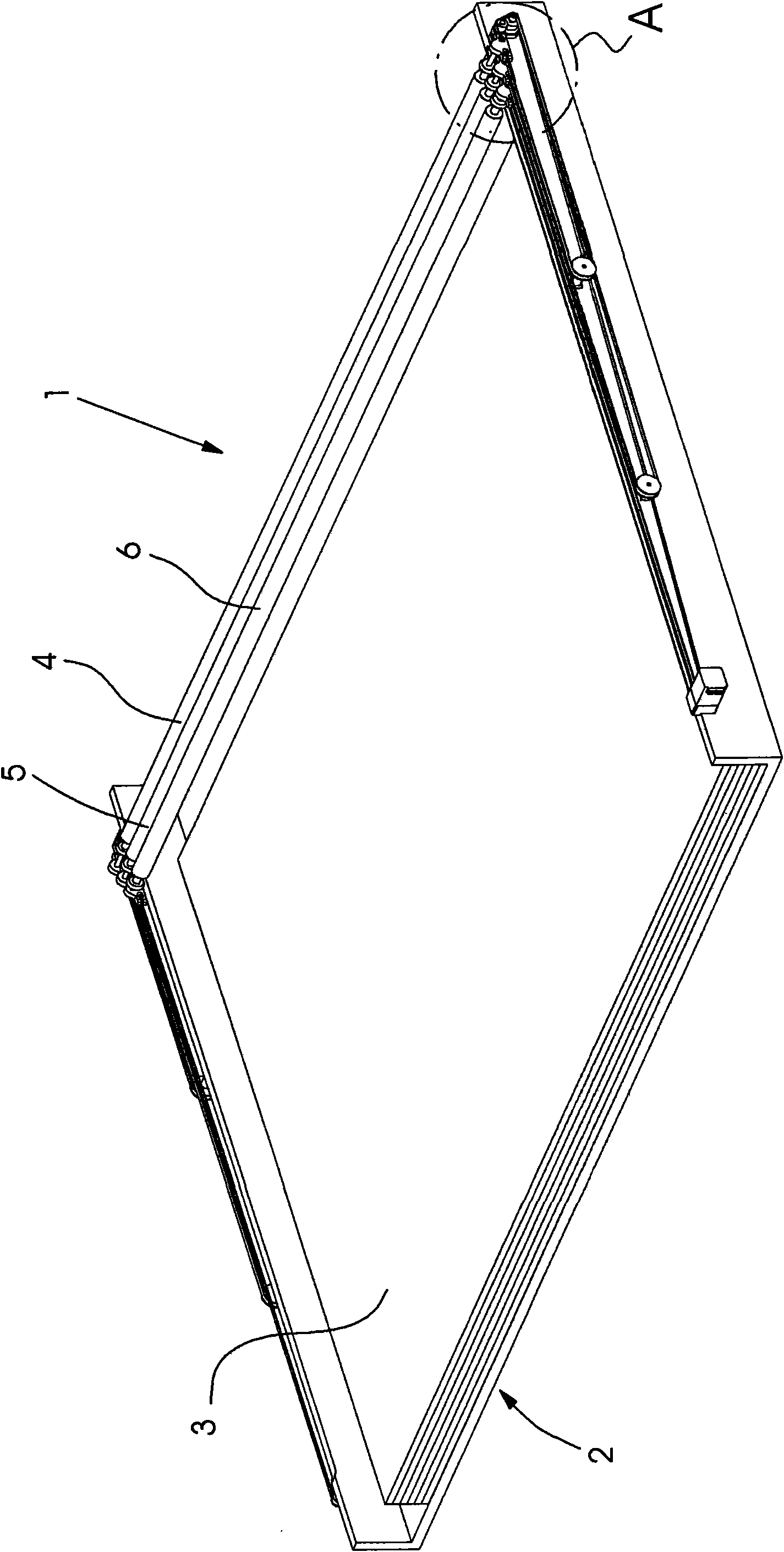
[0030] figure 1 A separating device 1 is shown, which is fed with printing plates 3 in the form of stacks via a printing plate pallet 2 .

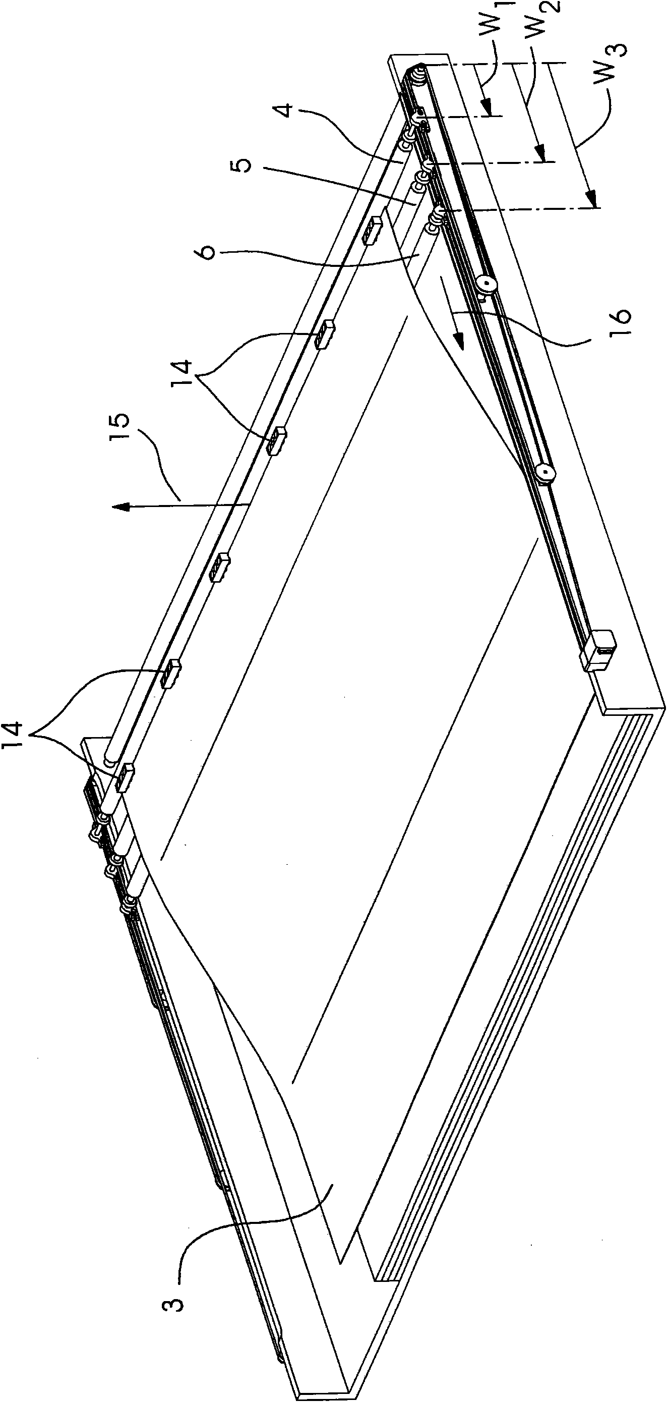
[0031] The separating device 1 has transverse beams 4 , 5 , 6 arranged one behind the other in a plane. The planes of these beams 4 , 5 , 6 lie above the printing plates 3 on the printing plate pallet 2 .

[0032] The drives 9, 10, 11 for these beams 4, 5, 6 are located at figure 1 In the region of local A.

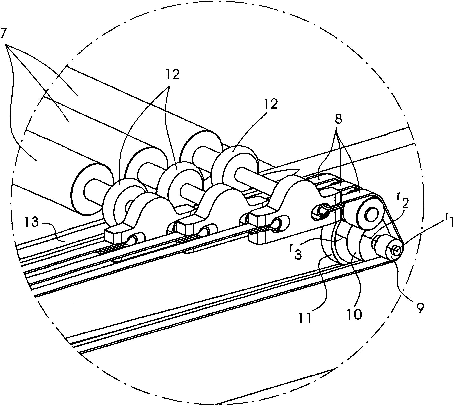
[0033] exist figure 2 shown in detail in figure 1 part of A.

[0034]These crossbeams 4 , 5 , 6 are arranged one behind the other and are driven by a belt 8 . For this purpose, the belts 8 are arranged next to each other in the same plane of movement of the transverse beams 4 , 5 , 6 . These beams 4 , 5 , 6 include rotatable rods 7 for moving under a raised printing plate 3 . In the example shown here, three transverse beams 4 , 5 , 6 with rods 7 are shown. The frontmost cross member 6 is connected via a belt 8 to a first pu...


PUM


Abstract

A device and a method for separating printing plates from a stack uses a lifting device for lifting the printing plates and at least one separating element to be moved under the lifted printing plates. The structurally simple device is able to react flexibly to different printing plate formats and, at the same time, avoids damage to a surface to be imaged of the individual printing plates. In order to avoid such problems, the device includes at least three separating elements (4, 5, 6) which, as they move under a lifted printing plate (3) at any time, are continuously disposed at distances from one another having a ratio that always remains constant (21, 21', 22 22').

Description

technical field [0001] The invention relates to a device for separating printing plates provided in a stack, which has a lifting device for lifting a printing plate from the stack and at least one The separate element under the printing plate. Furthermore, it relates to a method for separating printing plates provided in a stack, preferably using the device according to the invention, wherein the printing plates are lifted and at least one movable separating element is moved to the lifted from the bottom of the printing plate. Background technique [0002] In order to use a printing form in a method for printing a printing material inside a printing press, the printing forme is usually stretched as a printing form on a printing form cylinder of the printing press. These plates must be imaged in advance according to the image information. For imaging the printing plate, a further printing plate can be used, for example an exposed film, the information of which is transferr...

Claims


Application Information

Patent Timeline
IPC IPC(8): B65H3/50B65H3/08
CPCB65H3/50B65H3/0833B65H2701/1928
Inventor A·特里尔克
Owner HEIDELBERGER DRUCKMASHINEN AG
Why Eureka
Try Eureka