Aseptic filling valve

A technology of aseptic filling and valve body, applied in packaging, bottle filling, liquid bottling, etc., can solve the problems of large lifting displacement of valve stem mechanical mechanism, easy to bury hidden dangers, uneconomical and other problems

Active Publication Date: 2012-09-05
HANGZHOU ZHONGYA MACHINERY CO LTD
View PDF6 Cites 9 Cited by
  • Summary
  • Abstract
  • Description
  • Claims
  • Application Information

AI Technical Summary

Problems solved by technology

[0002] Present aseptic filling valves, such as the Chinese utility model patent whose publication number is CN2711133 and whose disclosure date is July 20, 2005, mostly adopt the method of driving the valve stem to move directly up and down to open and close the filling valve, that is, to drive the valve stem mechanically The mechanism and the valve stem are arranged up and down, and the working axis of the valve stem mechanical mechanism is coaxial with the lifting and lowering of the valve stem. In this way, the lifting displacement of the valve stem mechanical mechanism is large, and a larger or larger area is required between the aseptic area and the aseptic area. Complicated aseptic partition treatment is difficult and uneconomical, and it is easy to bury hidden dangers

Method used


Image

  • Aseptic filling valve
  • Aseptic filling valve

Examples


Embodiment Construction

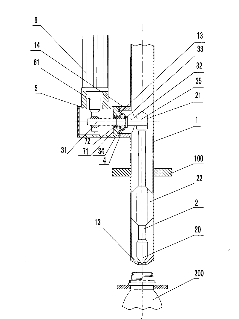
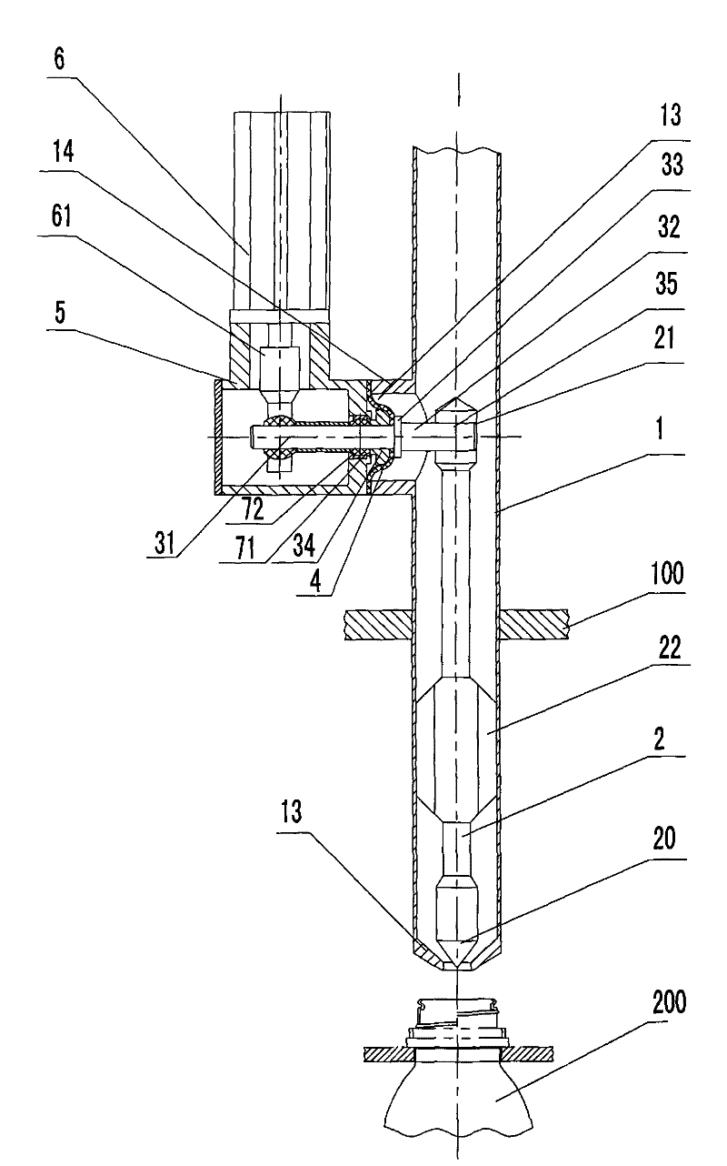
[0005] Refer to attached picture. The present invention includes a valve body 1, a valve stem 2 with a valve core 20, and reference numeral 22 is a guide wing on the valve stem.

[0006] The upper end of the valve body is connected to the liquid storage container that needs to be filled with liquid. For the convenience of installation, manufacturing, aseptic control and disinfection, the valve body includes a split upper valve body and a lower valve body. The upper valve body and the lower valve body are respectively installed on the The bracket 100 is mounted and sealed, and the mounting screw can pass through the bracket from the upper valve body and be threaded with the connecting blind hole of the lower valve body, so as to facilitate aseptic control and disinfection. The lower end of the lower valve body is a valve mouth 13, and the valve core 20 cooperates with the valve mouth 13 to realize the switch of the filling valve.

[0007] The present invention is provided with...


PUM


Abstract

The invention provides an aseptic filling valve, which comprises a valve body and a valve rod with a valve plug, and is provided with a lever driving the valve rod to lift; the lateral surface of the valve body is provided with a lever extending-in opening, and the lever extends into the valve body from the lateral surface of the valve body; and the aseptic filling valve is also provided with a flexible diaphragm which is in seal fit with the lever and encloses the valve body on the lever extending-in position. The aseptic filling valve can realize constant aseptic obstruction under the working condition of long-time frequent opening and closing so as to improve the safety of aseptic filling production; moreover, distances to a lever fulcrum are different, and the rotation amplitudes of the lever are different, so that manufacturers have more options to flexibly adopt an aseptic obstruction implementation proposal with economy, high reliability and easy realization according to actualconditions.

Description

technical field [0001] The invention relates to an aseptic filling valve. Background technique [0002] Present aseptic filling valves, such as the Chinese utility model patent whose publication number is CN2711133 and whose disclosure date is July 20, 2005, mostly adopt the method of driving the valve stem to move directly up and down to open and close the filling valve, that is, to drive the valve stem mechanically The mechanism and the valve stem are arranged up and down, and the working axis of the valve stem mechanical mechanism is coaxial with the lifting and lowering of the valve stem. In this way, the lifting displacement of the valve stem mechanical mechanism is large, and a larger or larger area is required between the aseptic area and the aseptic area. Complicated aseptic partition treatment is difficult and uneconomical, and it is easy to bury hidden dangers. Contents of the invention [0003] The technical problem to be solved by the present invention is to p...

Claims


Application Information

Patent Timeline
Patent Type & Authority Patents(China)
IPC IPC(8): B67C3/28
Inventor 史正史中伟吉永林侯高强
Owner HANGZHOU ZHONGYA MACHINERY CO LTD
Why Eureka
Try Eureka