Fluid ejecting apparatus

a technology of ejecting apparatus and ejecting chamber, which is applied in the direction of printing, etc., can solve the problems of increasing the size of the printer, the failure of the ejector, etc., and achieve the effect of not increasing the siz

Active Publication Date: 2010-05-13
SEIKO EPSON CORP
View PDF3 Cites 15 Cited by
  • Summary
  • Abstract
  • Description
  • Claims
  • Application Information

AI Technical Summary

Benefits of technology

[0011]An advantage of some aspects of the invention is that it provides a fluid ejecting apparatus capable of selectively sucking internal spaces of a plurality of caps without increasing the size.

Problems solved by technology

In such a printer, since a nozzle opens to a nozzle formation surface of a print head (fluid ejecting head), as an ink solvent evaporates from the nozzle, ink (fluid) is thickened, which may cause ink ejection failure.
Therefore, a space where the sled member protrudes needs to be ensured, and this causes a problem of an increase in the size of the printer.

Method used


Image

  • Fluid ejecting apparatus
  • Fluid ejecting apparatus
  • Fluid ejecting apparatus

Examples


first embodiment

[0051]Hereinafter, an ink jet printer according to an embodiment of the invention will be described with reference to the accompanying drawings. In addition, in the following description, in the case where a “front and rear direction”, an “up and down direction”, and a “left and right direction” are described, unless otherwise defined, they are matched with the “front and rear direction”, the “up and down direction”, and the “left and right direction” of FIG. 1 as a reference.

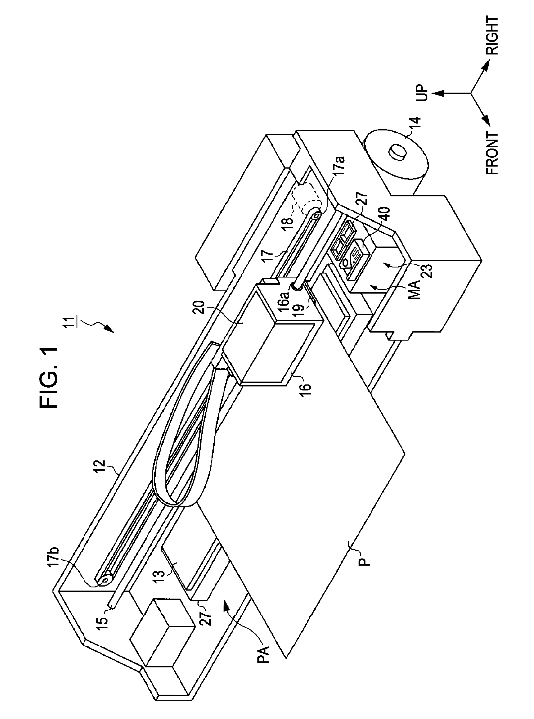
[0052]As illustrated in FIG. 1, an ink jet printer 11 as a fluid ejecting apparatus includes a frame 12 having a substantially rectangular box shape. In a lower portion of the frame 12, a platen 13 extends along the left and the right direction which is the longitudinal direction. On the platen 13, a printing sheet P is fed by a paper feed mechanism not shown from the rear side as a paper feed motor 14 provided below a rear surface of the frame 12 is driven.

[0053]Above the platen 13 in the frame 12, a guide sha...

second embodiment

[0125]Hereinafter, a second embodiment of the invention will be described mainly regarding differences thereof from the first embodiment.

[0126]In the second embodiment, as illustrated in FIGS. 10 and 11, the valve unit 40 of the first embodiment is changed to a valve unit 90. Specifically, the valve unit 90 includes a case member 91, both the pressing members 47 and 48, a cover member 92, the swing member 42, and a slider 93 for covering the upper surface of the cover member 92. Therefore, in the second embodiment, the swing member 42 is not supported by the lower surface of the carriage 16, and the convex portion 41 of the carriage 16 is omitted.

[0127]As illustrated in FIGS. 10 to 12, the case member 91 is configured by allowing a pair of hook portions 94 to extend outward (in the front and rear direction) from the upper end portions of the left end portions of both the front and rear side surfaces of the case member 46 of the first embodiment. The cover member 92 is configured by ...

third embodiment

[0136]Hereinafter, a third embodiment of the invention will be described mainly regarding the differences thereof from the first embodiment.

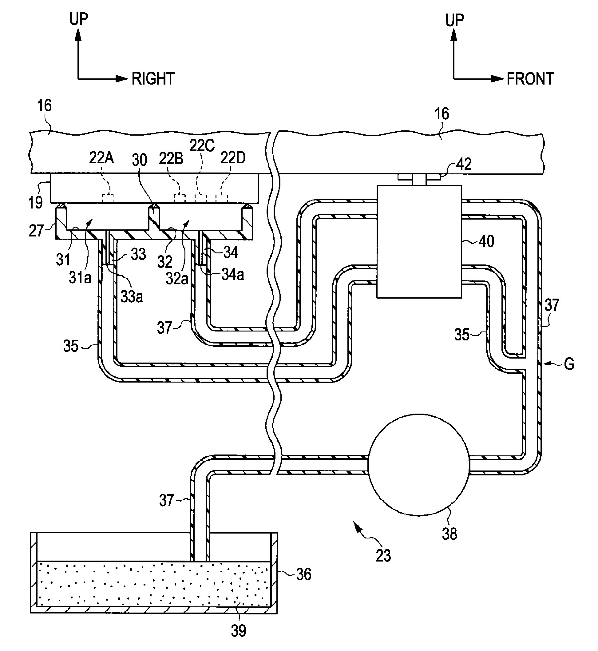
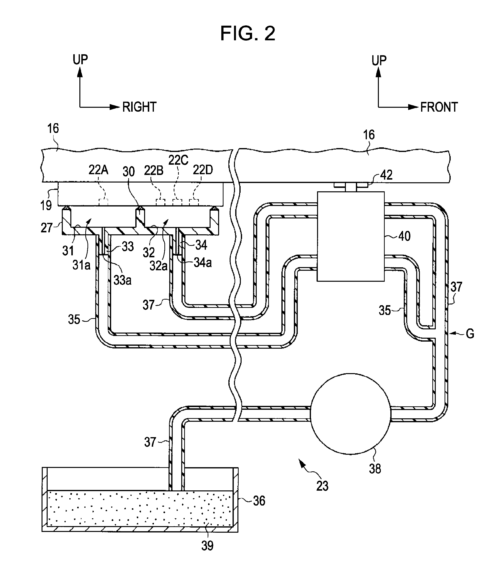
[0137]In the third embodiment, as illustrated in FIG. 14, first and second atmosphere opening tubes 110 and 111 for allowing the first and second cap internal spaces 31a and 32a to be open to the atmosphere are connected to the first and second cap portions 31 and 32 of the cap 27 of the first embodiment, and a valve unit 112 is provided in the middle of the first and second atmosphere opening tubes to selectively block them instead of the valve unit 40. Therefore, the first and second discharge tubes 35 and 37 are not provided with the blocking valve unit 40.

[0138]Specifically, as illustrated in FIG. 14, a third protruding portion 113 protrudes downward from the bottom wall of the first cap portion 31 to correspond to the first protruding portion 33, and a first communication passage 113a which communicates with the inside and the outside of th...


PUM


Abstract

A fluid ejecting apparatus includes: a carriage that supports a fluid ejecting head for ejecting fluid through a plurality of nozzles and is able to be reciprocated; a cap unit that comes in contact with the fluid ejecting head to form a plurality of cap internal spaces individually enclosing the nozzles; a suction unit that is able to suck the cap internal spaces via respective suction passages; and a selective blocking unit that is able to selectively block the suction passages as the carriage is reciprocated in a maintenance area for the maintenance of the fluid ejecting head, wherein the selective blocking unit includes: a blocking member that is reciprocated as the carriage is reciprocated in the maintenance area; and cam surfaces that engage with the blocking member as the blocking member is reciprocated to lead the blocking member to blocking positions for blocking the suction passages in order.

Description

BACKGROUND[0001]1. Technical Field[0002]The present invention relates to a fluid ejecting apparatus such as an ink jet printer.[0003]2. Related Art[0004]In general, as a kind of fluid ejecting apparatus for ejecting fluid toward a target from a nozzle provided in a fluid ejecting head, an ink jet printer (hereinafter, simply referred to as “printer”) is known. In such a printer, since a nozzle opens to a nozzle formation surface of a print head (fluid ejecting head), as an ink solvent evaporates from the nozzle, ink (fluid) is thickened, which may cause ink ejection failure. Accordingly, such a printer is generally provided with a head maintenance mechanism.[0005]The head maintenance mechanism is configured such that the mechanism includes a cap member which is able to come in contact with the print head to enclose the nozzle and a suction pump (suction unit) provided in an ink discharge passage connected to the cap member, and a negative pressure is generated in the cap member by d...

Claims


Application Information

Patent Timeline
Patent Type & Authority Applications(United States)
IPC IPC(8): B41J2/165
CPCB41J2/16532B41J2/16511
Inventor TOJO, SEIJI
Owner SEIKO EPSON CORP
Why Eureka
Try Eureka