Endotracheal intubation assist instrument

a technology of assist instruments and endotracheal intubation, which is applied in the field of endotracheal intubation assist instruments, can solve the problems of difficult control and placement of bronchofiberscopes from oral cavities, blockage of bronchofiberscope view fields, and difficulty in finding them, so as to achieve easy adjustment, improve the effect of bronchofiberscope placement and adjustmen

Inactive Publication Date: 2010-09-09
SENKO MED INSTR MFG CO LTD
View PDF19 Cites 15 Cited by
  • Summary
  • Abstract
  • Description
  • Claims
  • Application Information

AI Technical Summary

Benefits of technology

[0039]According to the configuration, the angle of elevation of the front edge of the guide tube against the bronchia wall can be adjusted easily by inflating the balloon. When the trachea cannot be observed by the view field of the bronchofiberscope via the side hole, the angle of the front edge of the guide tube and the view field of the bronchofiberscope can be adjusted easily by controlling the inflation of the balloon, and the trachea will be found more easily.

Problems solved by technology

However, it is difficult for the operator to control and insert the bronchofiberscope from the oral cavity to the trachea even though he can observe organs in the bronchofiberscope view field.
The first problem is that the bronchofiberscope view field often is blocked by the obstacles in the bronchofiberscope insertion operation.
There are a lot of obstacles present in the route from the oral cavity to the trachea.
The second problem is that the skilled hand is required for the bronchofiberscope operation.
Furthermore, the controllable angle is limited up to 90 degrees.
It is a comparably long tool, but the controllable portion is limited to the front edge portion of the fiberscope, so the usability is not enough for the operator.

Method used


Image

  • Endotracheal intubation assist instrument
  • Endotracheal intubation assist instrument
  • Endotracheal intubation assist instrument

Examples


embodiment 1

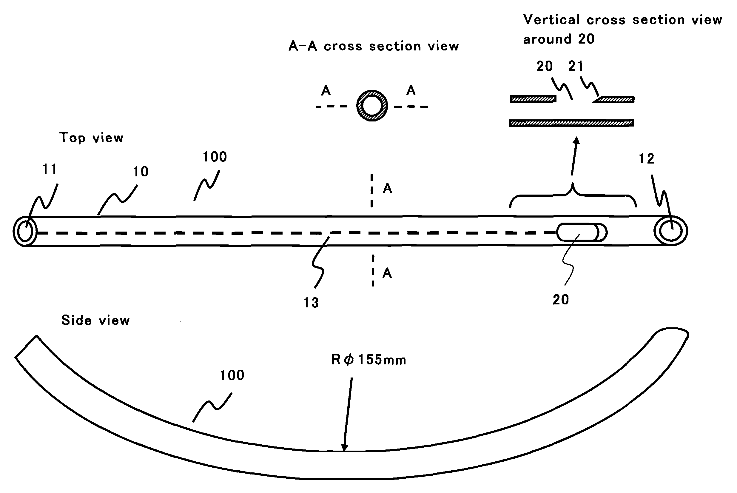
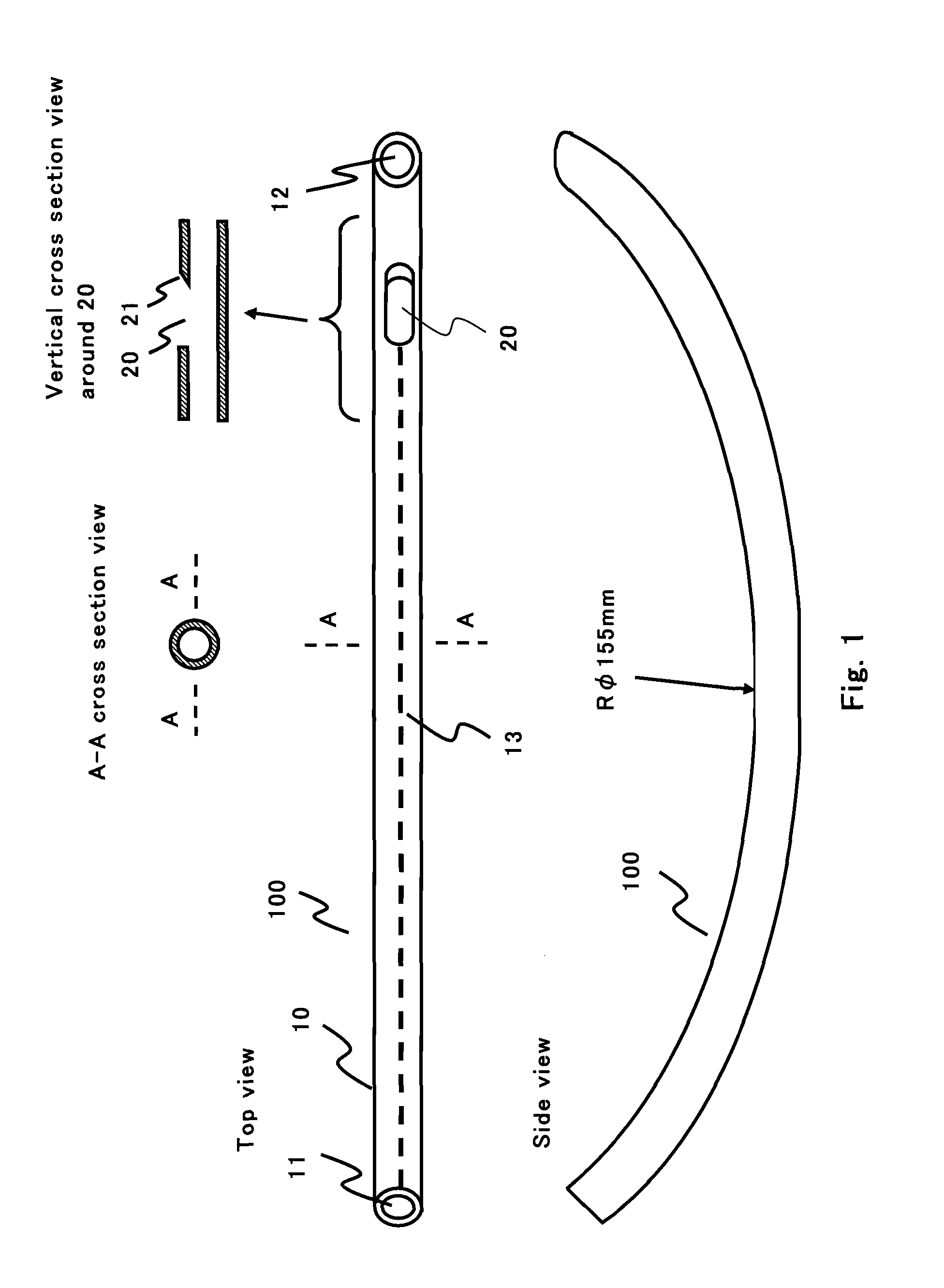
[0064]The first endotracheal intubation assist instrument 100 of this Embodiment 1 of the present invention is described below. FIG. 1 illustrates a basic structure of the first endotracheal intubation assist instrument 100. The central figure is the top view of the endotracheal intubation assist instrument 100, the lower figure is the right hand side view of the endotracheal intubation assist instrument 100. The upper figure is the cross section view along A-A line shown in the central figure and the vertical cross section view around the side hole 20. As shown in FIG. 1, the endotracheal intubation assist instrument 100 comprises a guide tube 10 and a side hole 20. The side hole 20 is provided as a part of the guide tube 10.

[0065]The guide tube 10 is made of material having both flexibility and appropriate structural strength. For example, it is made of a silicon tube. Flexibility is required for minimizing the damage to the patient's organs when the guide tube is inserted from th...

embodiment 2

[0094]The second endotracheal intubation assist instrument 100a of this Embodiment 2 of the present invention is described below. The cut assisting part installed in the guide tube wall of this second endotracheal intubation assist instrument 100a is different from that of the first endotracheal intubation assist instrument 100. The rest parts of this second endotracheal intubation assist instrument 100a are the same those of the first endotracheal intubation assist instrument 100. The cut assisting part installed in the guide tube wall of this second endotracheal intubation assist instrument 100a comprises a cut gap 14 installed from the terminal end opening up to the side hole 20 and a cover film 15 to cover the cut gap 14.

[0095]The upper figure of the FIG. 16 illustrates the cut gap 14 as the cut assisting part and the cover film 15 covering the cut gap 14 of the second endotracheal intubation assist instrument 100a. The lower figure of the FIG. 16 illustrates the view showing th...

embodiment 3

[0098]The third endotracheal intubation assist instrument 100b of this Embodiment 3 of the present invention is described below. There is no guide line on the inner wall of the guide tube 10 of the first endotracheal intubation assist instrument 100 of Embodiment 1. However in this Embodiment 3, there is a blue-green guide line 16 indicating on the inner wall from the terminal end up to the front edge of the guide tube 10b of the third endotracheal intubation assist instrument 100b of Embodiment 3.

[0099]FIG. 17 illustrates the view showing the developed appearance of the inside wall of the guide tube 10b. There is a blue-green guide line 16 indicating on the inner wall from the terminal end up to the front edge of the guide tube 10b. The guide line 16 gives several merits. The first merit is that it is easy for the operator to verify the positioning status of the guide tube 10 in the patient's organs. It is assumed that the endotracheal intubation assist instrument is inserted into ...


PUM


Abstract

The present invention provides an endotracheal intubation assist instrument for inserting the bronchofiberscope from the oral or nasal cavity to the trachea easily and then inserting the endotracheal tube into the trachea easily. The side hole 20 is installed near the front edge of the guide tube 10. The guide tube 10 advances naturally from the oral cavity, and the front edge of the guide tube 10 reaches the entrance of the esophagus. The view field is obtained by putting the front edge of the bronchofiberscope 200 onto the base 21. The glottis can be found by the view field of the bronchofiberscope 200 while pulling back the guide tube 10 slowly. The path for the bronchofiberscope 200 from the oral cavity to the esophagus can be secured by the guide tube 10 without influence of the obstacles such as a tongue and an epiglottis, and the operatability can be enhanced. Only the guide tube 10 is removed and the bronchofiberscope 200 remains as the guide line for the endotracheal tube insertion. The endotracheal tube is inserted to the trachea by utilizing the bronchofiberscope 200 as the guide line.

Description

TECHNICAL FIELD[0001]The present invention relates to an endotracheal intubation assist instrument for inserting an endotracheal tube into a patient's trachea, when artificial respiration is required for the patient who has an airway difficulty. The airway difficulty is the leading cause of death during a general anesthesia operation. For example, the present invention can be applied to a tool for assisting the endotracheal intubation under the bronchofiberscope observation which is used for the patient having a severe difficulty in the endotracheal intubation.BACKGROUND ART[0002]An endotracheal intubation is required in a medical rescue scene for managing the airway maintenance of the patient who has an airway difficulty. For example, the endotracheal intubation is required for the patient whose airway is collapsed by an accident, the patient who cannot manage breathe by himself in a coma state or in a drunk state, the patient whose spontaneous breathing is decreased or stopped in ...

Claims


Application Information

Patent Timeline
Patent Type & Authority Applications(United States)
IPC IPC(8): A61M16/04
CPCA61B1/00154A61B1/267A61B1/2676A61M16/0411A61M25/01A61M2205/583A61M16/0418A61M16/0488A61M16/0479A61M16/0461A61M16/0459A61M16/0404
Inventor UESUGI, TAKANOBU
Owner SENKO MED INSTR MFG CO LTD
Why Eureka
Try Eureka