Lock-up mechanism for slippage door and slippage door

A technology of locking mechanism and sliding door, which is applied in the field of sliding door, can solve problems such as influence of service life of guide wheel, drop, positioning failure, etc., and achieve the effect of simple and compact structure, simple structure and low cost

Inactive Publication Date: 2011-01-12
SANY AUTOMOBILE MFG CO LTD
View PDF4 Cites 0 Cited by
  • Summary
  • Abstract
  • Description
  • Claims
  • Application Information

AI Technical Summary

Problems solved by technology

When these engineering vehicles are actually used, the operator basically opens the door for operation, so it needs to be positioned after the door is opened. The existing automatic positioning technology basically decelerates the lower guide wheel by friction, and through the friction force. Limit the front and back movement of the door when it opens, and limit the guide wheel through friction, which has a great impact on the service life of the guide wheel. At the same time, the aging and wear of the friction elements may lead to positioning failure and eventually the positioning cannot be achieved.
Another positioning method is to manually pull out a stop pin after opening the door to prevent the door from sliding and closing by itself. Although this mechanism is reliable, it cannot realize the automatic opening function. It is very inconvenient to use and is basically not used in practical applications.
[0003] At the same time, if the plane guide rail guide structure is adopted, no matter which method is adopted, the door will overturn due to the sharp deceleration of the lower guide wheel when the door is opened at high speed, and the sliding door may derail without other protective measures. In case of direct fall
Therefore, as the planar guide rail with simpler structure, it has not been popularized.
In addition, for construction machinery, when the door is opened and locked during operation, the vibration and bumps of the machine may cause the door and the car body to resonate together, resulting in resonance in the up and down directions. If there are no good protective measures, May cause door load wheels to fail

Method used


Image

  • Lock-up mechanism for slippage door and slippage door
  • Lock-up mechanism for slippage door and slippage door
  • Lock-up mechanism for slippage door and slippage door

Examples


Embodiment Construction

[0023] The present invention will be further described in detail below in conjunction with specific embodiments and accompanying drawings.

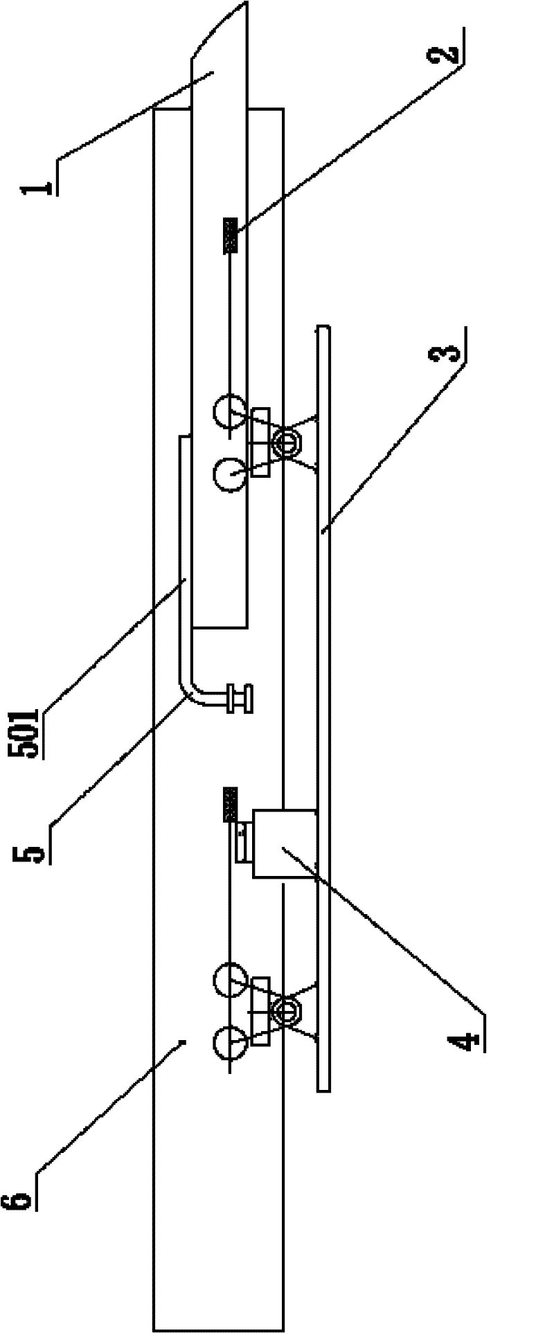
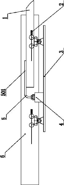
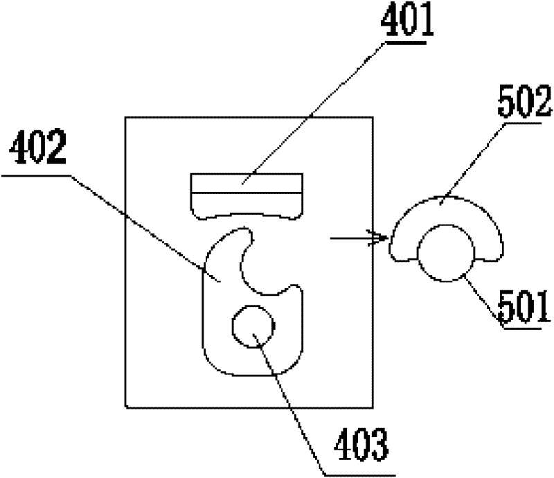
[0024] Such as figure 1 with figure 2 As shown, the present invention is used for the locking mechanism of the sliding door, and it comprises the fixed locking pile 5 and the positioning lock block device 4 installed on the door body 3, and the positioning lock block device 4 is connected with the door body 3 after the door body 3 is opened. The locking pile 5 cooperates to lock and locate the door body 3 . In this embodiment, the driver's cab applied to an engineering vehicle is taken as an example. The locking pile 5 is fixed on the vehicle body 1 and remains still, and the door body 3 can slide on the guide rail 6 to complete the opening and closing. see image 3 , Figure 4 with Figure 5 The positioning lock block device 4 includes a vertical limit block 401 and a dead bolt 402. The dead bolt 402 is fixed on the door body 3 thr...


PUM


Abstract

The invention discloses a lock-up mechanism for a slippage door and the slippage door. The slippage door comprises a lock stud and a locking block positioning device, wherein the lock stud is fixed and keeps still; the locking block positioning device is arranged on a door body; and when the door body is opened, the locking block positioning device is matched with the lock stud to position the door body. The slippage door is provided with the lock-up mechanism. The lock-up mechanism for the slippage door provided by the invention has simple and compact structure and low cost, completes the opening function automatically, and has good lock-up effect and wide applicable range.

Description

technical field [0001] The invention mainly relates to the field of sliding doors, in particular to a locking mechanism for a sliding door and the sliding door. Background technique [0002] The sliding door is easy to open and has the characteristics of saving space when opening. Therefore, in the prior art, the sliding door is widely used in the control rooms of automobiles, excavators, and cranes. When these engineering vehicles are actually used, the operator basically opens the door for operation, so it needs to be positioned after the door is opened. The existing automatic positioning technology basically decelerates the lower guide wheel by friction, and through the friction force. The front and rear movement of the door is restricted, and the guide wheel is restricted by friction, which has a great impact on the service life of the guide wheel. At the same time, the aging and wear of the friction elements may lead to positioning failure and eventually the positioning...

Claims


Application Information

Patent Timeline
Patent Type & Authority Patents(China)
IPC IPC(8): E05C17/50E06B3/46
CPCE05B65/0811
Inventor 李建芳徐亚非邹云玲张召春
Owner SANY AUTOMOBILE MFG CO LTD
Why Eureka
Try Eureka