
Electric disk brake

A disc brake, electric technology, applied in the direction of brake type, brake components, brake actuators, etc., can solve the problems of large-scale deceleration mechanism, can not meet the increase of output, etc., to achieve the effect of large thrust

Active Publication Date: 2009-12-02
HITACHI LTD
View PDF1 Cites 17 Cited by
  • Summary
  • Abstract
  • Description
  • Claims
  • Application Information

AI Technical Summary

Problems solved by technology

[0005] However, the electric disc brake using the conventional speed reduction mechanism has the following problem: when the speed reduction ratio is increased, the speed reduction mechanism is enlarged.
In addition, there is a problem that the electric disc brake using two rotary / direct motion conversion mechanisms cannot satisfy the increase in output

Method used


Image

  • Electric disk brake
  • Electric disk brake
  • Electric disk brake

Examples


Embodiment Construction

[0023] Hereinafter, embodiments of the present invention will be described in detail with reference to the drawings.

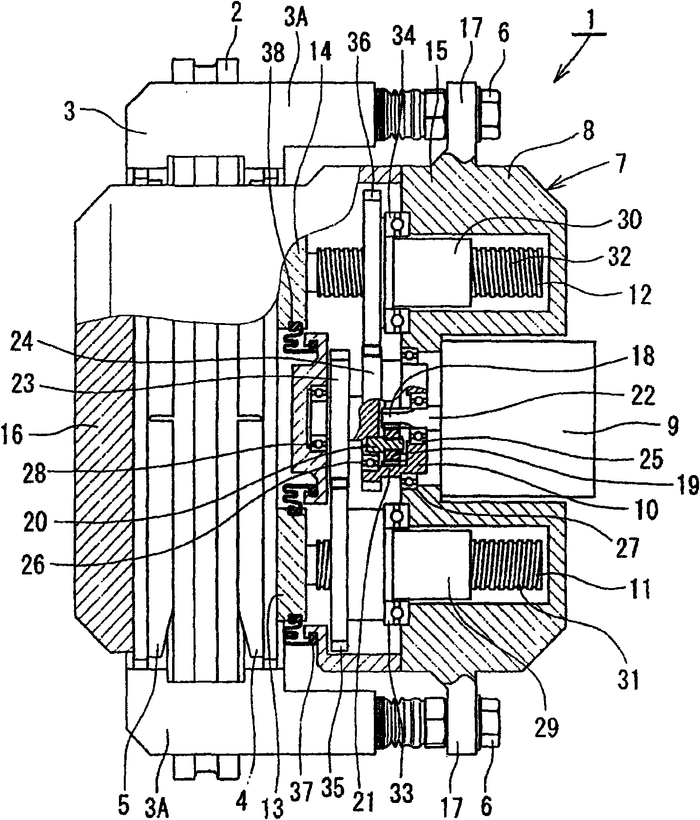
[0024] For the first embodiment of the present invention, refer to figure 1 and figure 2 Be explained. Such as figure 1 As shown, the electric disc brake 1 of this embodiment is a caliper floating type disc brake, and includes: a disc rotor 2 that rotates together with the wheel; (not shown); a pair of brake blocks 4, 5, which are arranged on both sides of the disc rotor 2 and supported by the bracket 3; electric pliers 7, which are arranged in a manner straddling the disc rotor 2, and pass A pair of slide pins 6 , 6 is supported by a pair of arm portions 3A, 3A of the bracket 3 so as to be movable in the axial direction of the disk rotor 2 .

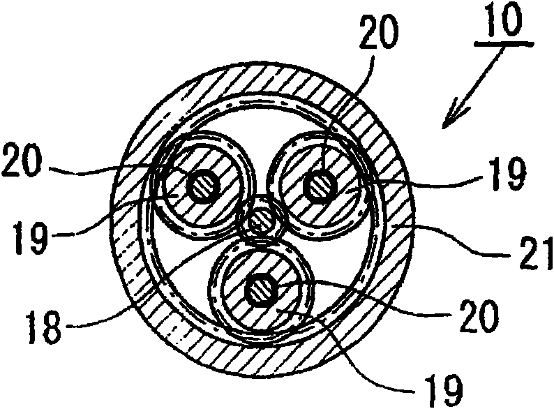
[0025] The electric pliers 7 are assembled with the following elements on the pliers main body 8, namely, a motor / control unit 9 (electric motor), a speed reduction mechanism 10, a pair of ball screw mechanisms 11,...


PUM


Abstract

There is provided with an electric disk brake which is a small sized and is able to obtain large braking block pressure and run stably. The electric disk brake drives a sun gear of a reducing mechanism (10)(satellite gear mechanism) by an output shaft (22) of an electric motor / control unit (9), drives a ball screw mechanism (11) through a first output gear (23) by the rotation of a satellite gearrack (20), drives a ball screw mechanism (12) through a second output gear (24) by the rotation of a gear ring (21), and generates braking force by pressing braking blocks (4, 5) to a disk rotor. Theelectric disk brack can obtain double output by leading both the satellite gear rack (20) and the gear ring (21) of the satellite gear mechanism comparing with the condition that one of the satellitegear rack (20) and the gear ring (21) is fixed and the other is output, in addition, using differential rotation, even if one of driving ball screw mechanisms (11, 12) is stuck caused by fault, whichcan generate braking force.

Description

technical field [0001] The invention relates to an electric disc brake, which generates a braking force by pressing a brake block to a disc rotor through an electric motor. Background technique [0002] As an electric disc brake, it is known to convert the rotary motion of the motor rotor into the linear motion of the piston by using a rotary / direct motion conversion mechanism such as a ball screw mechanism and a ball slide mechanism, so that the brake pad moves in a circular motion. The disc rotor presses to generate braking force. The electric disc brake can generate a desired braking force by detecting the driver's brake pedal force (or displacement) and the like by a sensor, and controlling the rotation of an electric motor by a control device based on the detected value. [0003] In such an electric disc brake, as disclosed in Patent Document 1, a reduction mechanism using a spur gear is interposed between the rotation / linear conversion mechanism and the electric motor...

Claims


Application Information

Patent Timeline
Patent Type & Authority Applications(China)
IPC IPC(8): F16D65/18
CPCF16D2125/40F16D2125/36F16D2125/56F16D65/183F16D65/568F16D2121/24F16D2125/48F16D2125/50
Inventor 坂下贵康
Owner HITACHI LTD
Learn More