
Machine vision based fatigue driving monitoring method and system

A fatigue driving and machine vision technology, which is applied in the monitoring of fatigue driving and safe driving of vehicles, can solve the problems of slow image processing speed, affecting the accuracy of fatigue state, and low accuracy, so as to improve the processing speed and efficiency, Reduce data processing volume, improve accuracy and effectiveness

Inactive Publication Date: 2009-12-02
SHEHNCHZHEHN SAFDAO TECH KORPOREJSHN
View PDF0 Cites 75 Cited by
  • Summary
  • Abstract
  • Description
  • Claims
  • Application Information

AI Technical Summary

Problems solved by technology

[0006] 1. The positioning of the driver's face and eyes is not accurate
Due to the large individual differences in driver's face and eye features, when the existing monitoring method is used to locate the face and eyes of various drivers, the accuracy is very low, and the position of the feature points of the upper and lower eyelids and the position of the eyebrows Individual differences are also large, which affects the accuracy of judging the degree of eye closure, and ultimately affects the accuracy of judging the fatigue state
[0007] 2. Image processing efficiency is not high
The processing speed of the collected image is slow, and it takes a few seconds to judge a frame of image, which makes it impossible to monitor the driver's fatigue state in time
In the driving process, the driver often appears drowsy (such as dozing off) or distracted in a short period of time. If the driver cannot be monitored and reminded in time, the significance of fatigue monitoring will be greatly reduced.
[0008] 3. In the image processing process, the existing methods (such as the existing active shape model method) are greatly affected by light, and the accuracy of judgment is low

Method used


Image

  • Machine vision based fatigue driving monitoring method and system
  • Machine vision based fatigue driving monitoring method and system
  • Machine vision based fatigue driving monitoring method and system

Examples


Embodiment Construction

[0031] The present invention will be further described in detail below through specific embodiments in conjunction with the accompanying drawings.

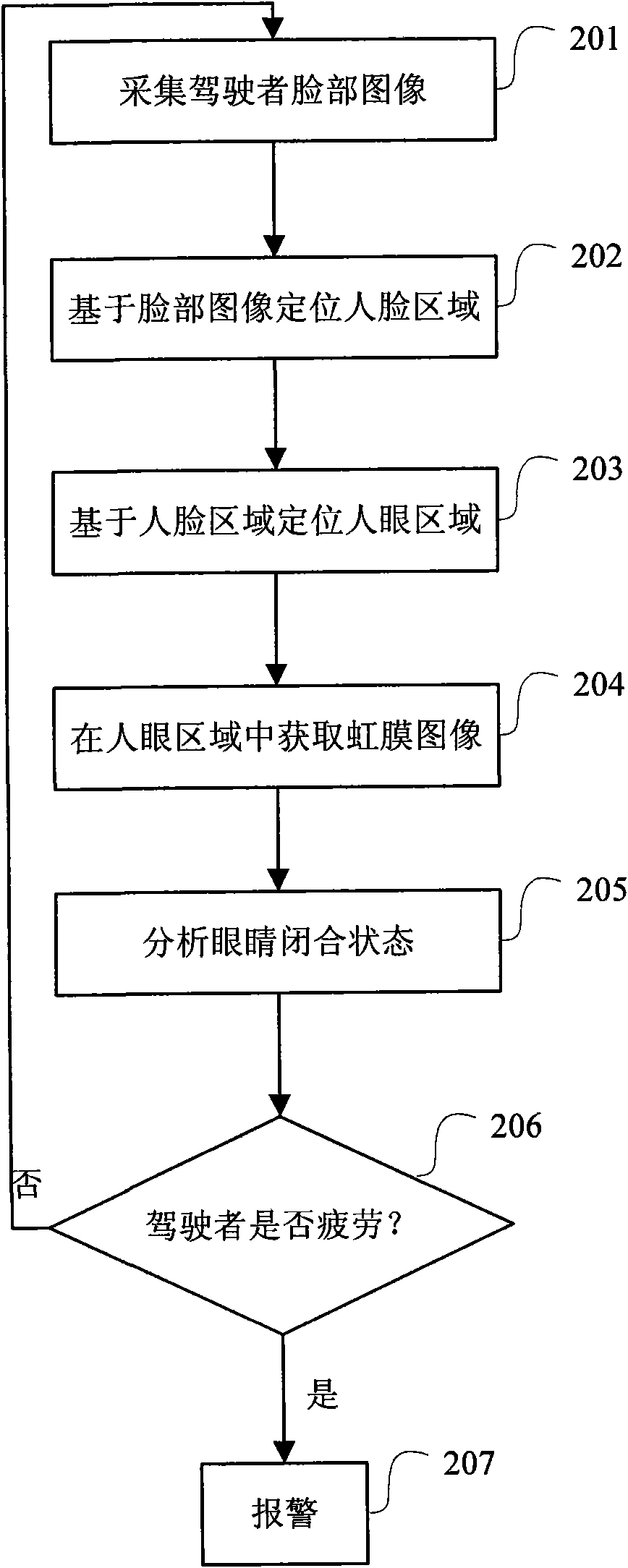
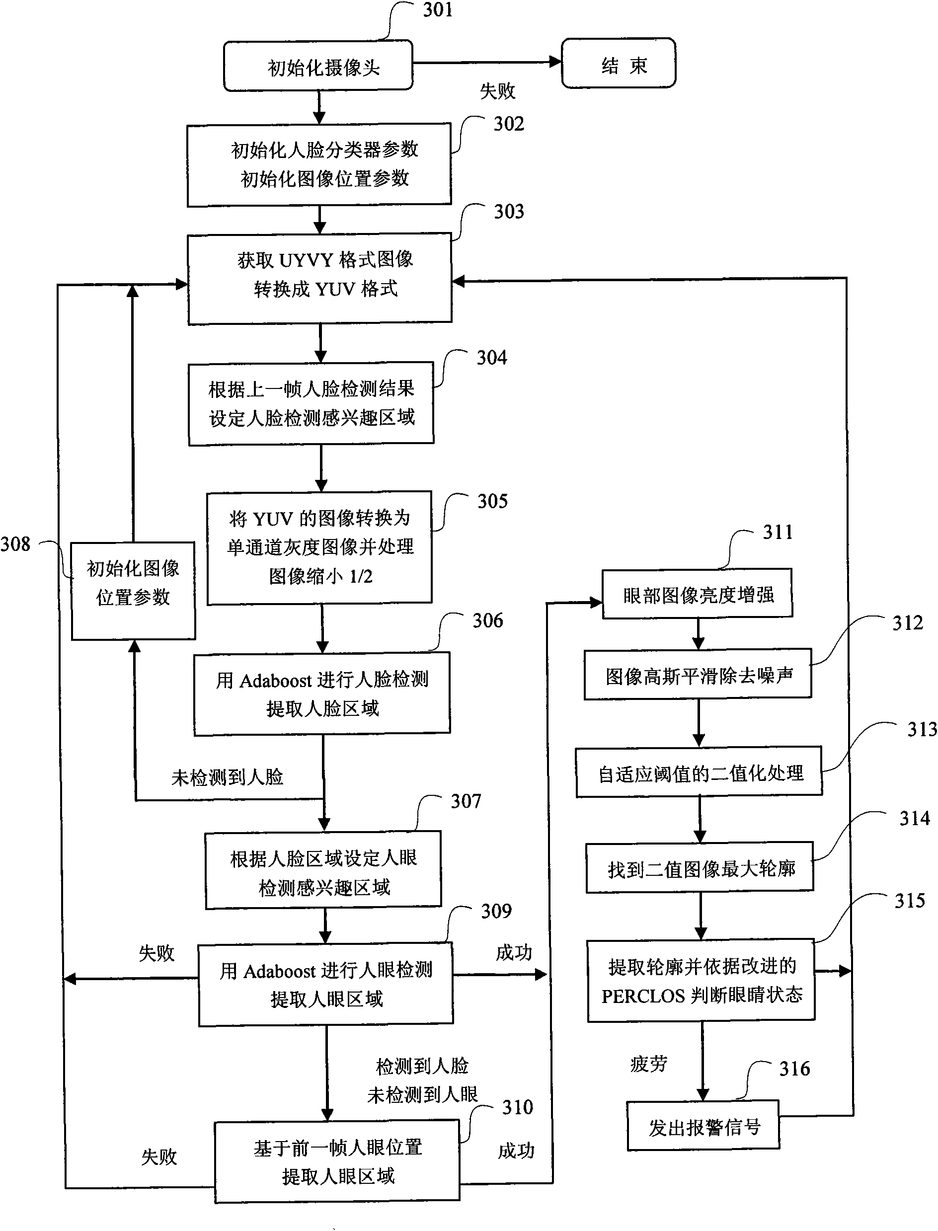
[0032] The present invention acquires real-time images through a camera, extracts the driver's facial features and eye feature images, and then performs a series of image processing and calculations on the extracted area to obtain the driver's eye closure degree and time parameters, combined with The fatigue judgment standard judges whether the driver is dealing with the fatigue state.

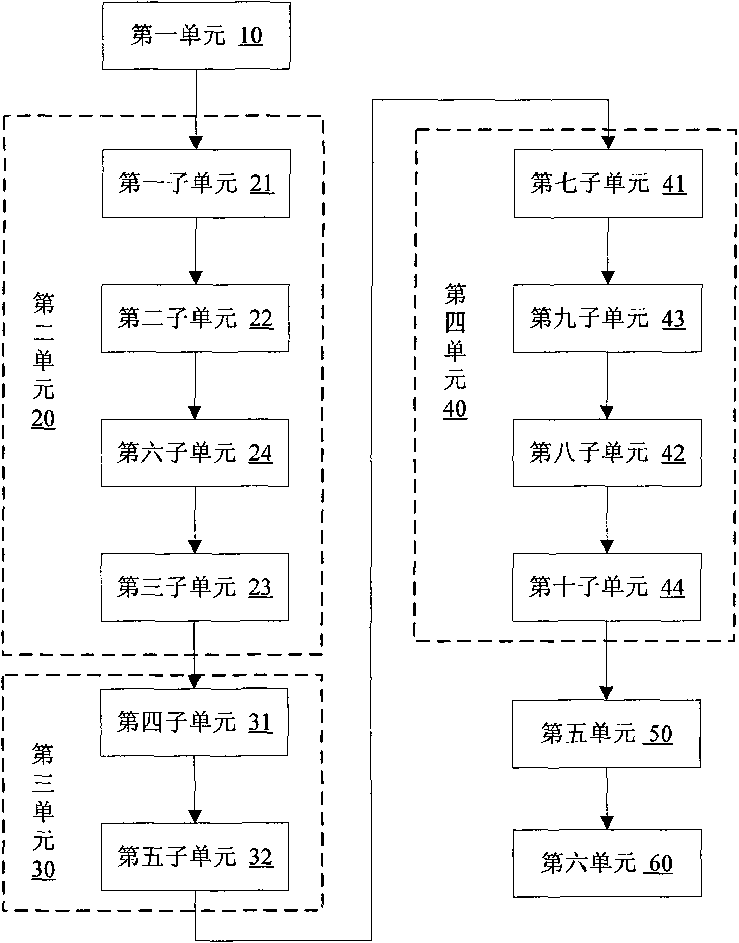
[0033] Please refer to the structural diagram of an embodiment of the present invention figure 1 As shown, the fatigue driving monitoring system includes a first unit 10 , a second unit 20 , a third unit 30 , a fourth unit 40 , a fifth unit 50 and a sixth unit 60 . The first unit 10 is used to collect the driver's face image, the second unit 20 is used to locate the face area based on the face image, and the third unit 30 is used to locate the hu...


PUM


Abstract

The invention discloses a machine vision based fatigue driving monitoring method and a machine vision based fatigue driving monitoring system. The method comprises the following steps: A1, acquiring a face image of a driver; B1, positioning a human face area according to a pre-trained human face feature classifier based on the face image; C1, positioning a human eyes area according to a pre-trained human eyes feature classifier based on the human face area; D1, acquiring an iris image in the human eyes area; E1, analyzing an eyes closing state based on the iris image; and F1, comparing the eyes closing state and a fatigue standard to judge whether the driver is in a fatigue state. The method and the system detect the human face and the human eyes through the human face classifier and the human eyes classifier respectively, reduce the influence of individual difference on a detection result, reduce the influence of lighting and human face gestures on the detection result, and improve the accuracy of eyes positioning and eyes closing judgment of the driver so as to improve the accuracy of fatigue judgment.

Description

【Technical field】 [0001] The invention relates to the technical field of safe driving of vehicles, in particular to the technical field of fatigue driving monitoring. 【Background technique】 [0002] Fatigue driving is one of the important hidden dangers of today's traffic safety. When the driver is in a state of fatigue, the ability to perceive the surrounding environment, the ability to judge the situation, and the ability to control the vehicle are all reduced to varying degrees, and traffic accidents are prone to occur. Therefore, the research and development of high-performance real-time monitoring and early warning technology of driver fatigue status can effectively reduce the hidden dangers caused by fatigue driving, so as to achieve the purpose of ensuring the personal safety of drivers and the safety of related personnel around them. [0003] The driver fatigue detection system refers to the sampling of information such as driver physiological signals, driver physio...

Claims


Application Information

Patent Timeline
IPC IPC(8): G08G1/01G06T1/00G06T7/60
Inventor 吴泽俊程如中赵勇王强
Owner SHEHNCHZHEHN SAFDAO TECH KORPOREJSHN
Learn More