Method for quickly positioning oscillating center of electric system

An oscillation center and power system technology, applied in the direction of reducing/preventing power oscillation, electric vehicles, electrical devices, etc., can solve the problem of not being able to determine the exact position of the oscillation center, not being able to adapt to the power grid, and not being able to provide out-of-step decoupling and other issues, to achieve the effect of flexible and convenient use, fast criterion and strong adaptability

Active Publication Date: 2009-12-02
CHINA ELECTRIC POWER RES INST +1
View PDF0 Cites 20 Cited by
  • Summary
  • Abstract
  • Description
  • Claims
  • Application Information

AI Technical Summary

Problems solved by technology

The traditional oscillation separation device cannot determine the exact position of the oscillation center of the system. Usually, low voltage or impedance circle is used to determine whether the oscillation center is within the separation range. These criteria can only give an approximate range, and the out-of-step solution The column cannot provide better selectivity, so it cannot better adapt to the new requirements of the third line of defense of my country's interconnected grid
[0004] The traditional methods for locating the oscillation center include the impedance method, the minimum voltage divided by the current method, etc., each

Method used


Image

  • Method for quickly positioning oscillating center of electric system
  • Method for quickly positioning oscillating center of electric system
  • Method for quickly positioning oscillating center of electric system

Examples


Embodiment Construction

[0024] The following is a preferred example of the present invention, and the technical solutions realized by the present invention will be further described below in conjunction with the accompanying drawings.

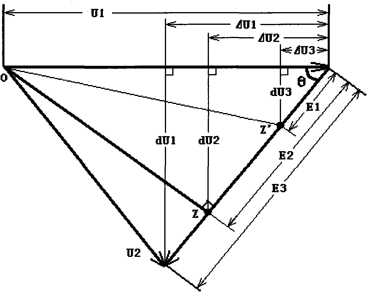
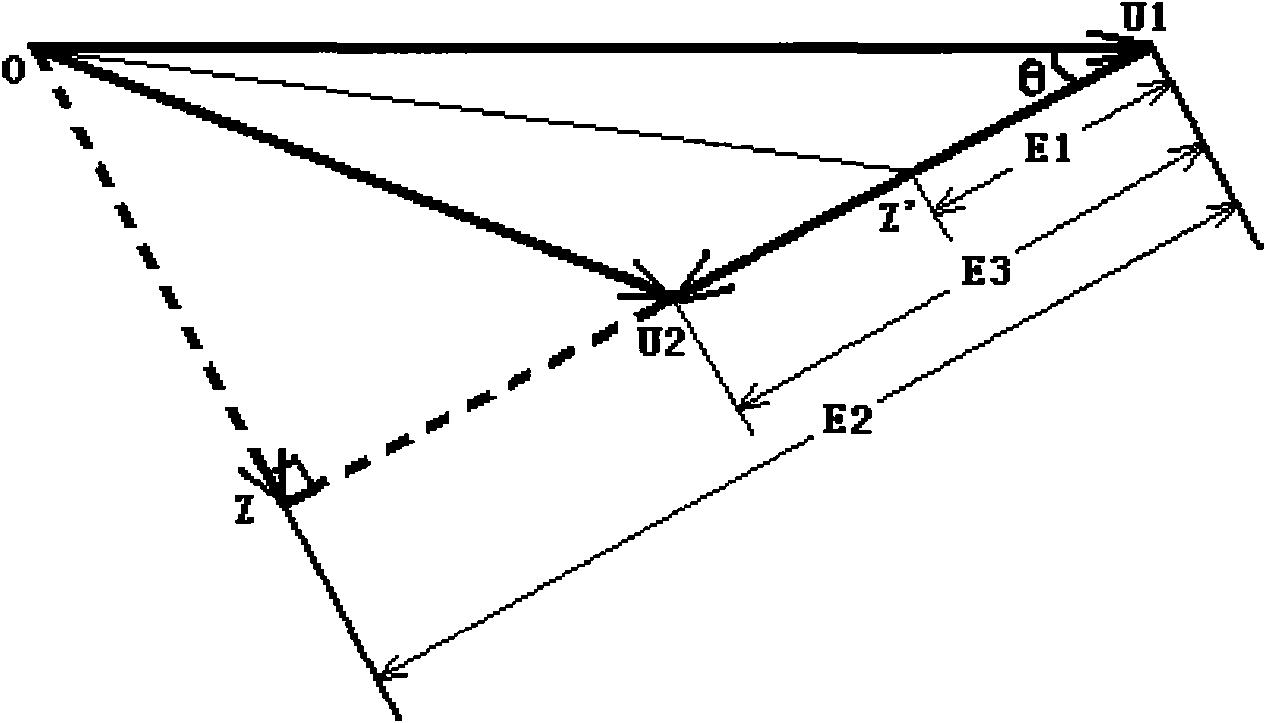
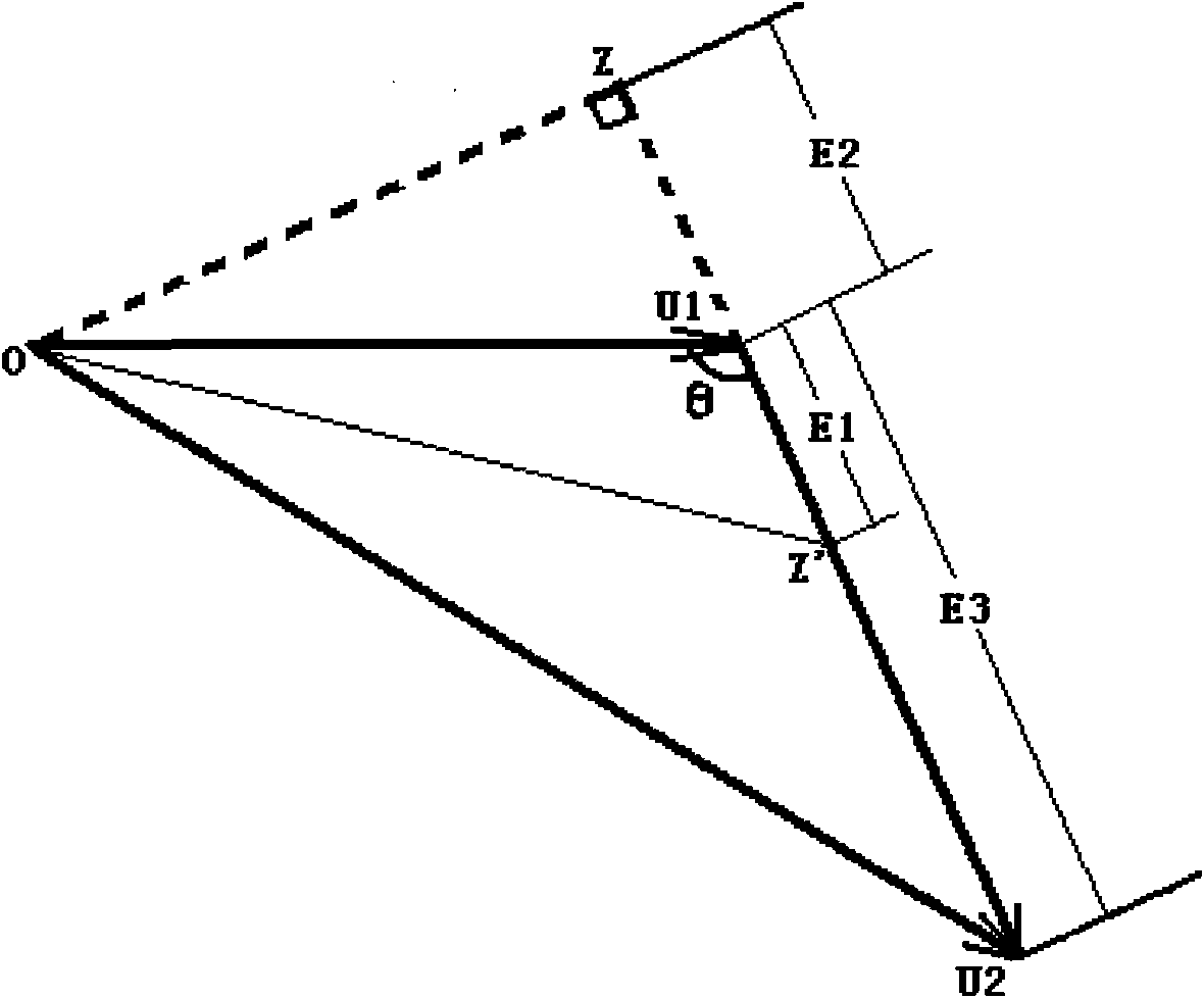
[0025] as attached figure 1 Shown is the calculation method for the center of oscillation within the protection zone. u 1 is the voltage phasor at the beginning of the line measured at the installation point of the device, U 2 To measure the voltage phasor at the end of the line, E 3 is the potential difference between the beginning and the end, and θ is the line impedance angle. In the triangle shown in the figure, Z' is any point on the line, and the connecting line OZ' is the voltage phasor at point Z'. When Z' coincides with Z, that is, OZ' is perpendicular to U 1 with U 2 When connecting the lines, the voltage phasor represented by OZ' takes the minimum value. Since the current value is the same everywhere on the line, and the impedance is evenly distribut...


PUM


Abstract

The invention provides a method for quickly positioning the oscillating center of an electric system. In application aspects of inhibiting the oscillation of the system, coordinating the disconnection and the like, the accurate position of the oscillating center of the electric system often needs to be known. By the method, only the electric quantity and natural parameters of circuits need to be measured on the spot, the out-of-step oscillating center of the system can be accurately judged at the synchronous oscillation stage of the system, and the out-of-step quick disconnection criterion is realized based on the on-the-spot electric quantity. By the popularization and the application of the method for positioning the oscillating center based on the on-the-spot electric quantity, and the combination of the reliable quick disconnection criterion, the out-of-step disconnection control can be realized quickly, reliably and on the spot, and the method can also be adapted to different operating modes of the system, and realize the coordinating control of a plurality of disconnection devices.

Description

technical field [0001] The invention relates to the field of power system automation, in particular to a method for quickly locating the oscillation center of a power system. Background technique [0002] Improving the security and stability of the power system is the top priority of the power operation department. In the "Guidelines for Power System Safety and Stability" promulgated by our country, it stipulates three levels of safety and stability standards for the ability of my country's power grid to withstand large disturbances. When a serious failure cannot maintain synchronous and stable operation, it is necessary to prevent the system from crashing and minimize load loss. Disassembly is an important means of control to meet the above-mentioned third-level safety and stability standards and prevent the system from collapsing completely. [0003] Decoupling the oscillating system at the center section of the out-of-step oscillation can quickly calm the system oscillat...

Claims


Application Information

Patent Timeline
IPC IPC(8): H02J3/24G01R19/00G01R21/00G01R27/02
Inventor 王俊永王慧铮许勇熊敏蒋宜国王英涛李刚张金平
Owner CHINA ELECTRIC POWER RES INST
Why Eureka
Try Eureka