
Control method for shield tunnel axis having underground structure on adjacent side

A technology for underground structures and shield tunnels, applied in tunnels, tunnel linings, underground chambers, etc., can solve the problems of not considering the release effect, and the measures for correcting the deviation of the tunnel axis are not perfect. Effect

Inactive Publication Date: 2009-12-09
SHANGHAI JIAO TONG UNIV
View PDF0 Cites 18 Cited by
  • Summary
  • Abstract
  • Description
  • Claims
  • Application Information

AI Technical Summary

Problems solved by technology

This paper does not take into account the existence of underground structures near the tunnel and the release of pore water pressure accumulation during construction, and does not take any measures in the surrounding strata to weaken the high pressure that affects the control of the shield axis
In addition, the measures to correct the deviation of the tunnel axis are not perfect.

Method used


Image

  • Control method for shield tunnel axis having underground structure on adjacent side
  • Control method for shield tunnel axis having underground structure on adjacent side
  • Control method for shield tunnel axis having underground structure on adjacent side

Examples


Embodiment

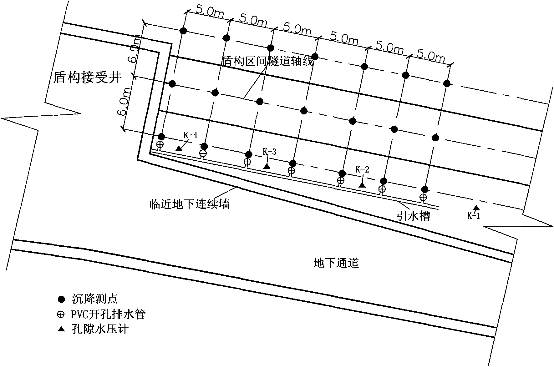
[0038] There is an underground passage to be built next to the tunnel of a certain subway section. The underground diaphragm wall of the passage has been completed, and it passes through the side of the section tunnel at close range. The underground diaphragm wall of the channel is connected with the end shield receiving well in an L shape.

[0039] Such as figure 1 As shown, there is an underground diaphragm wall plan on the side of the shield, and the specific implementation steps are as follows:

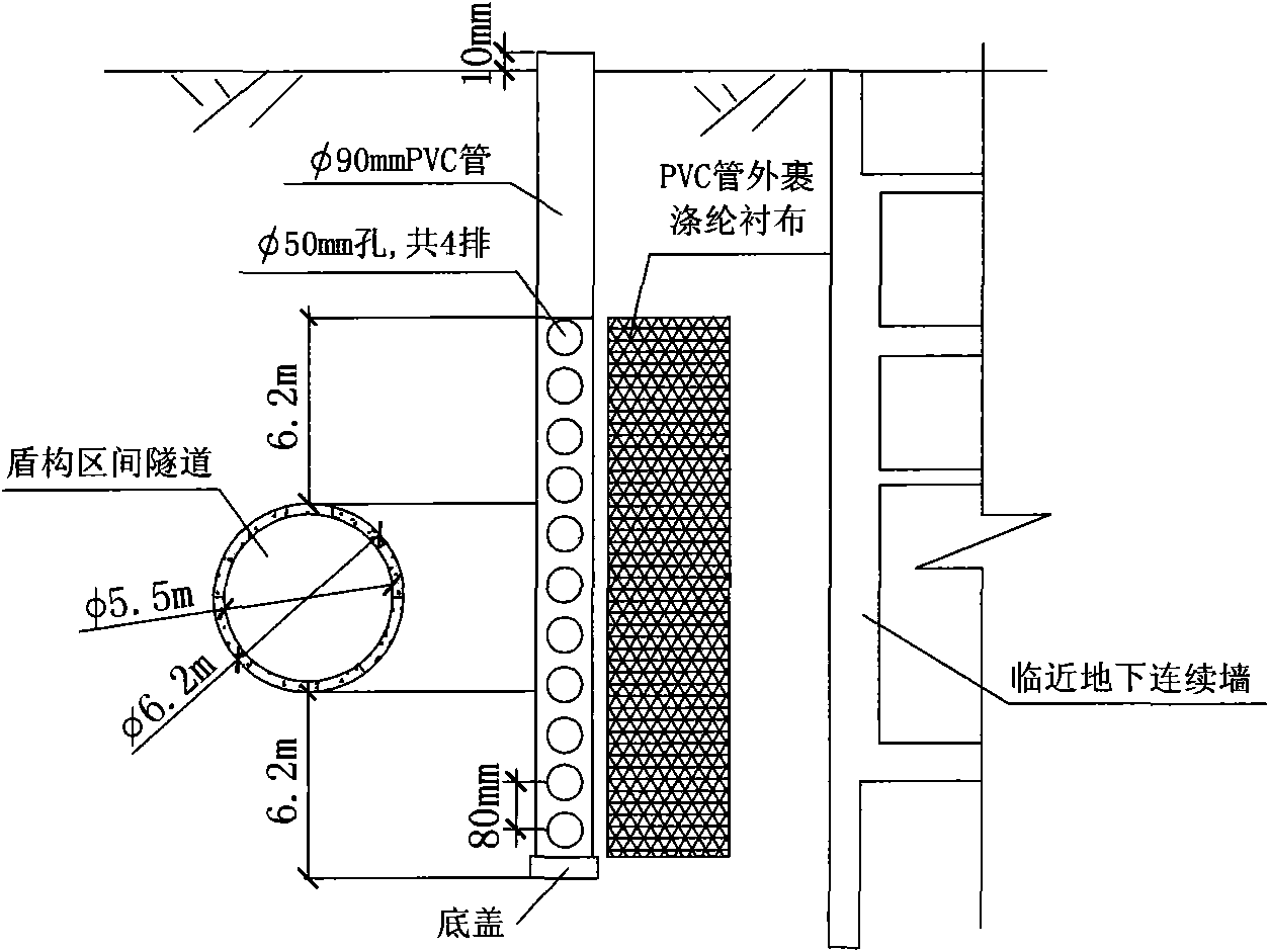
[0040] (1) The buried depth of the tunnel top is H=9m, the outer diameter of the tunnel is D=6.2m, and L=3.8m. The length of the three-dimensional finite element model is 200m, the width is 60m, and the height is 50m. After finite element calculation, determine L 1 =60m,L 2 =30m, key control section L 2 Inside, the distance between the tunnel and the underground diaphragm wall is 3.8m~5.8m.

[0041] (2) Set the distance L 2 The section of the 20th ring is used as the trial p...


PUM


Abstract

The invention relates to a control method for a shield tunnel axis having an underground structure on an adjacent side, comprising the following steps: using a three-dimensional finite element model to numerically stimulate the shield, setting a range L1 in which the underground structure starts influencing on near pass-through of the shield and a length L2 of the segment in which priority needs to be given to the tunnel axis; regarding a segment that is 20 meters away from the focused protection segment L2 as an experimental advancing section of the shield; installing a PVC pipe having the diameter of d1 and an opening on the side thereof in the soils between the shield tunnel and the adjacent underground structure in the range L2 determined by step (1), increasing channels from which pore water is drained and decreasing aggregation of pressure of the pore water; accurately measuring indicators that control the quality of the tunnel axis; and monitoring and real-time regulating. The invention solves the problem that the control of the shield tunnel axis is influenced by the existence of the underground structure, guarantees normal usage of the underground structure and quality control of the shield tunnel axis, and is suitable for similar working conditions.

Description

technical field [0001] The invention relates to a method in the technical field of construction engineering, in particular to a method for controlling the axis of a shield tunnel when there is an underground structure adjacent to the side. Background technique [0002] Due to the acceleration of urban construction and the continuous expansion of construction scale, the utilization rate of underground space is increasing day by day, and various underground structures are becoming denser and denser. In addition, in order to alleviate the pressure of urban traffic, it also accelerated the pace of subway construction and the formation of a network structure of subway routes. In the process of urban development, due to the influence of planning and design lag and the limitation of construction funds, it will become increasingly common for subway construction to pass through existing underground structures at close range. [0003] The shield method tunnel construction is to use t...

Claims


Application Information

Patent Timeline
Patent Type & Authority Applications(China)
IPC IPC(8): E21D9/00E21D11/00
Inventor 孙阳罗春泳沈水龙
Owner SHANGHAI JIAO TONG UNIV
Learn More