

Self-lubricating bearing
A technology of self-lubricating bearings and bearings, which is applied in the direction of bearings, bearing components, shafts and bearings, etc., can solve the problems of shortening the service life of self-lubricating bearings, reducing the oil content of self-lubricating bearings, bearing friction, etc., to prevent oil spills or leakage Oil, good self-lubricating effect, effect of prolonging service life
- Summary
- Abstract
- Description
- Claims
- Application Information
AI Technical Summary
Problems solved by technology
Method used
Image

Examples
Embodiment Construction
[0030] In order to achieve the above-mentioned purpose and effect, the technical means and the structure adopted by the present invention are hereby drawn to describe in detail the features and functions of the preferred embodiments of the present invention as follows.
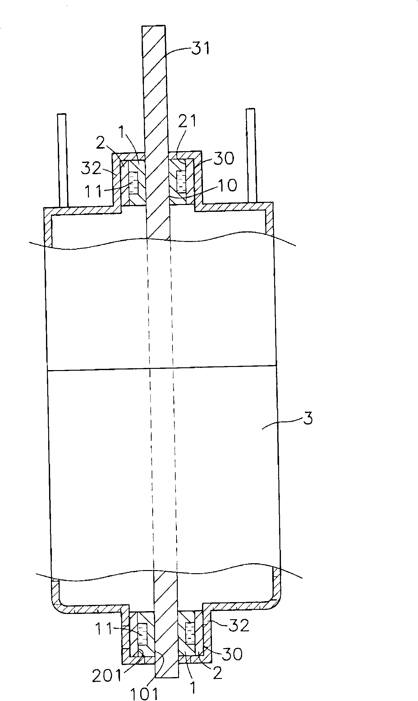
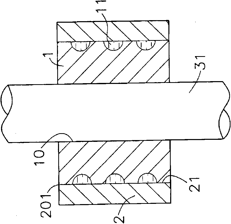
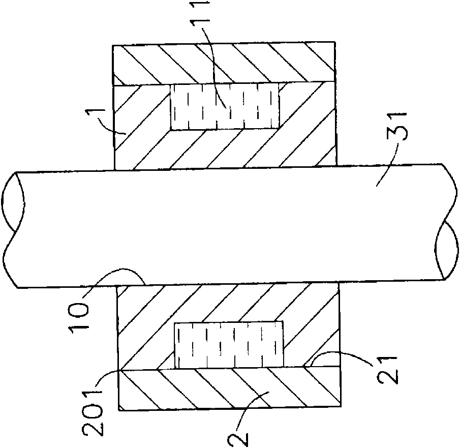
[0031] see figure 1 , figure 2 , image 3 , Figure 4 Shown are the side view partial sectional view of the motor of the preferred embodiment of the present invention, the side view sectional view of the first embodiment, the side view sectional view of the second embodiment, and the side view sectional view of the third embodiment. It can be clearly seen that the self-lubricating bearing of the present invention is composed of a shaft core 31 including a bearing 1, a housing 2 and a motor 3, wherein:
[0032] The bearing 1 can be made of a porous material (such as a ceramic material), and has a through central shaft hole 10 inside, and an oil storage tank 11 can be provided on the inside or outer surface ...
PUM
 Abstract
Description
Claims
Application Information