Multi-gear simultaneous meshing variable speed unit

A transmission and meshing technology, which is applied in the field of multi-speed simultaneous meshing transmissions, can solve problems such as low transmission efficiency, complex structure, troublesome manipulation, etc., and achieve the effects of improving productivity, reducing manufacturing costs, and being easy to maintain

Inactive Publication Date: 2009-12-09
吴志强
View PDF4 Cites 3 Cited by
  • Summary
  • Abstract
  • Description
  • Claims
  • Application Information

AI Technical Summary

Problems solved by technology

[0002] At present, all transmissions with gears need to go through mechanisms such as gear shifting and manipulation to achieve gear shifting, so the structure is complicated, the manipulation is troublesome, and the cost is high; in addition, the transmission efficiency is low

Method used


Image

  • Multi-gear simultaneous meshing variable speed unit
  • Multi-gear simultaneous meshing variable speed unit
  • Multi-gear simultaneous meshing variable speed unit

Examples


Embodiment 1

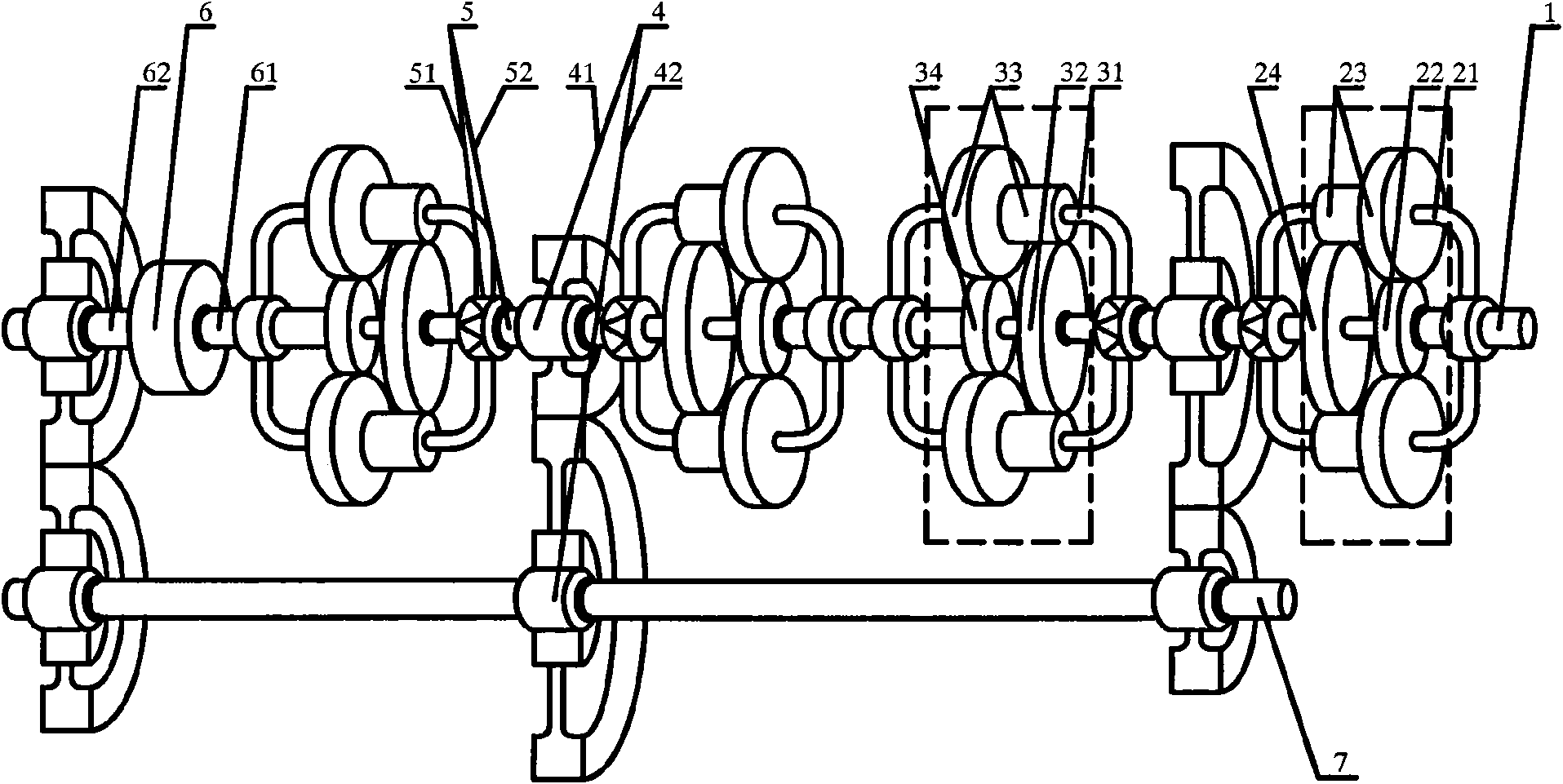
[0036] like figure 1As shown in , a multi-speed simultaneous meshing transmission includes an input shaft 1, a transmission mechanism 4, a one-way clutch 5, a coupling 6, and an output shaft 7. The output end 62 of the coupling 6 is matched with the transmission mechanism 4 The input end 41 of each transmission mechanism 4 is connected with the output shaft 7, and two torque increasing units 2 and two speed regulating units 3 are arranged between the input shaft 1 and the output shaft 7. Unit 2 includes an output element 21, an input element 22, a planetary gear 23, and a coupling element 24. The speed regulating unit 3 includes an output element 31, an input element 32, a planetary gear 33, and a coupling element 34. The input element 22 is connected with the input shaft 1, and the input elements 22 of the remaining torque boosting units 2 are connected with the coupling elements 34 of the previous speed regulating unit 3 respectively, and the coupling element 34 of the last ...

Embodiment 2

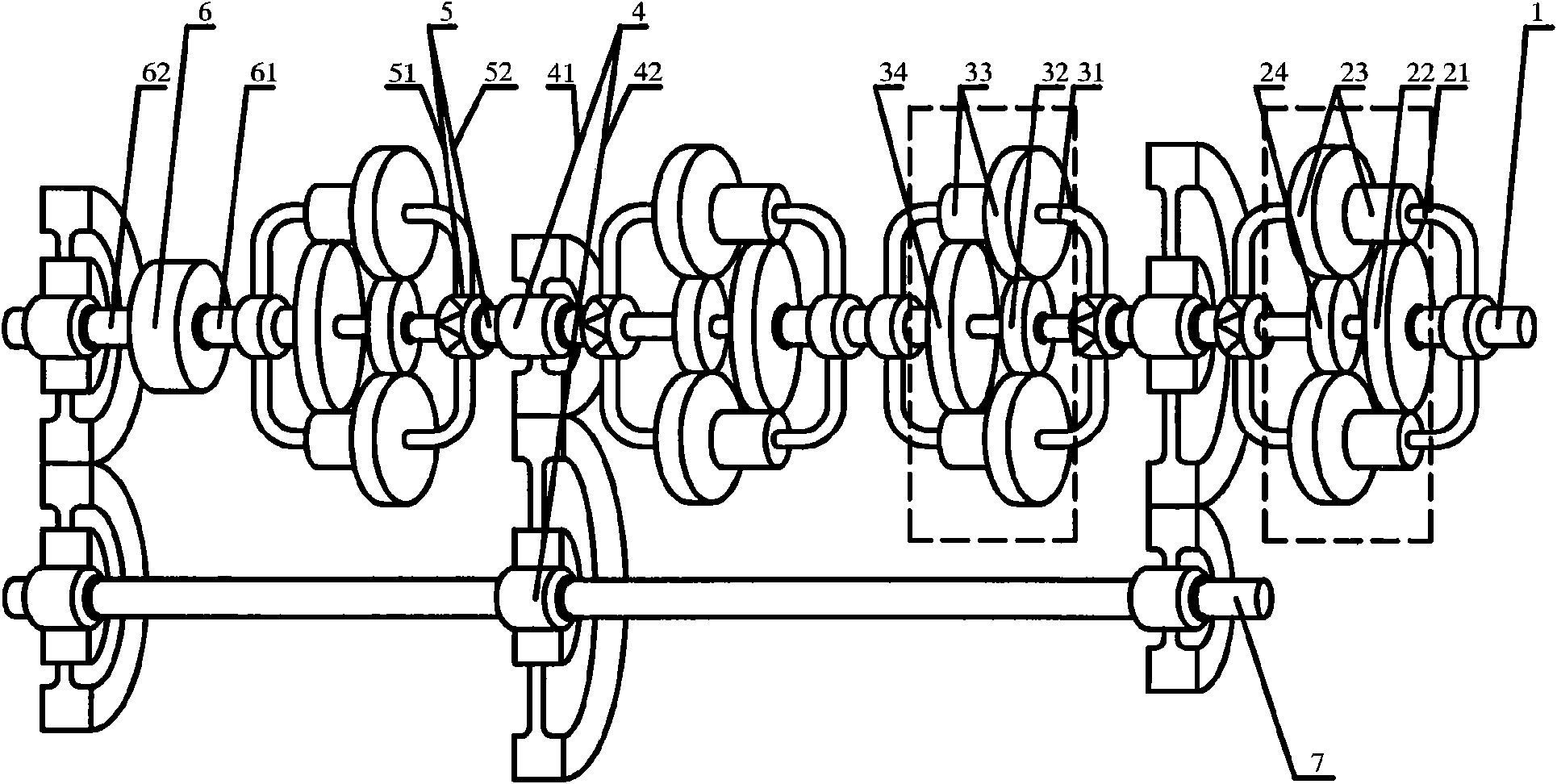
[0043] like figure 2 As shown in , this embodiment only exchanges the positions of the torque booster unit 2 and the speed regulation unit 3 that cooperate with each other in the first embodiment, and its working principle and realized functions and effects remain unchanged.

Embodiment 3

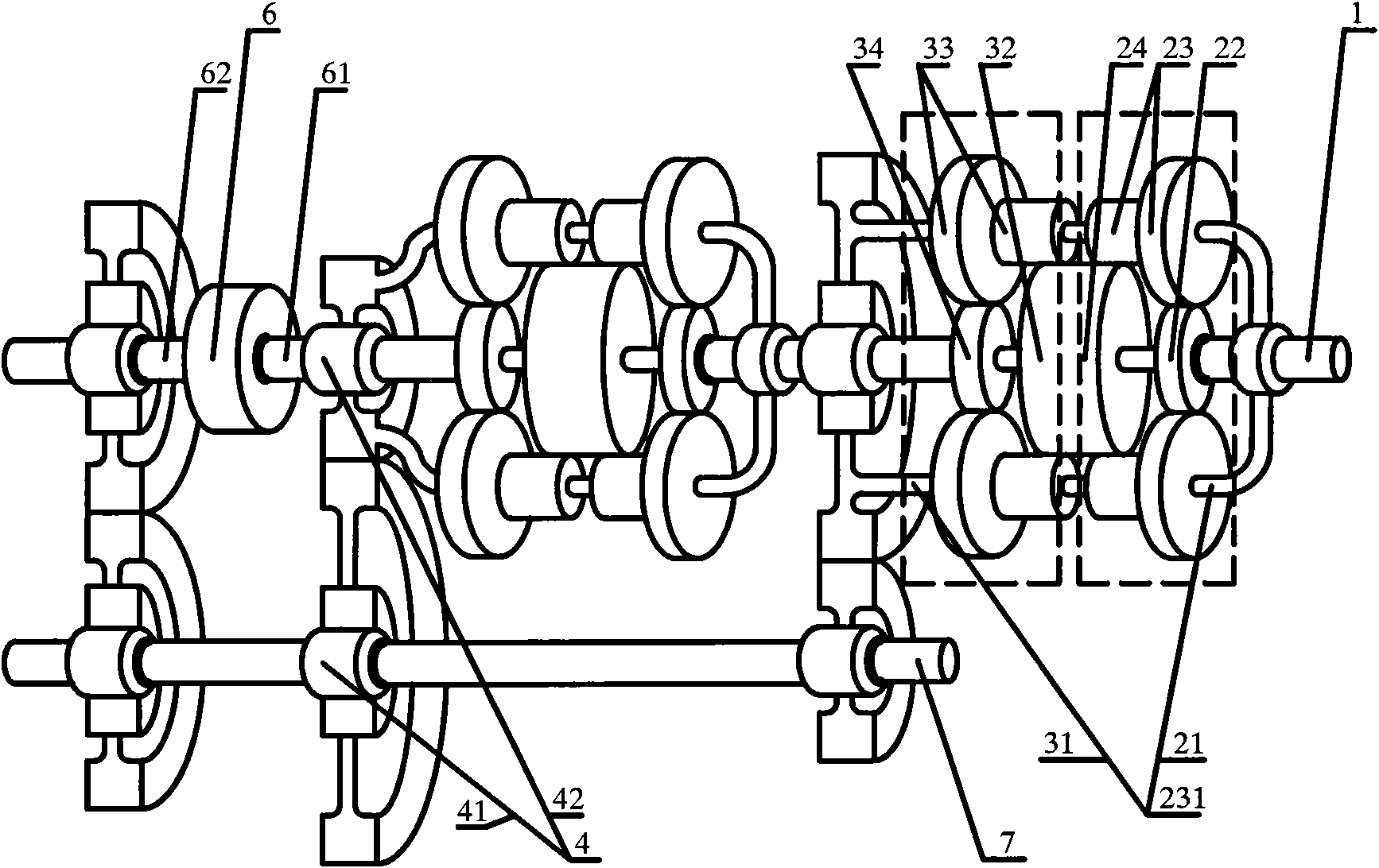
[0045] like image 3 As shown in , it includes an input shaft 1, a transmission mechanism 4, a coupling 6, and an output shaft 7. The output end 62 of the coupling 6 is connected with the input end 41 of the matching transmission mechanism 4, and the output of each transmission mechanism 4 The end 42 is connected with the output shaft 7, two torque increasing units 2 and two speed regulating units 3 are arranged between the input shaft 1 and the output shaft 7, the input element 22 of the first torque increasing unit 2 is connected with the input shaft 1, and the rest The input element 22 of the torque increasing unit 2 is connected with the coupling element 34 of the previous speed regulating unit 3 respectively, the coupling element 34 of the last speed regulating unit 3 is connected with the input end 61 of the coupling 6, and the coupling elements of each torque increasing unit 2 24 is connected with the input element 32 of the next speed regulating unit 3 respectively, an...


PUM


Abstract

The invention provides a multi-gear simultaneous meshing variable speed unit which has the technical scheme that the output end 62 of a connector 6 is connected with the input ends 41 of matched transmission mechanisms 4; the output ends 42 of all transmission mechanisms 4 are connected with an output shaft 7; an input component 22 of a first torque increase unit 2 is connected with an input shaft 1; input components 22 of other torque increase units 2 are connected with connecting components 34 of respective previous speed regulation units 3; a connecting component 34 of the last speed regulation unit 3 is connected with the input end 61 of the connector 6; connecting components 24 of all torque increase units 2 are connected with input components 32 of respective next speed regulation units 3; output components 21 of all torque increase units 2 and output components 31 of respective next speed regulation units 3 are connected with the input ends 51 of respectively matched one-way clutches 5; and the output ends 52 of the one-way clutches 5 are connected with the input ends 41 of the transmission mechanisms 4 respectively matched with the torque increase units 2 and the speed regulation units 3.

Description

technical field [0001] The invention belongs to the field of transmissions, more specifically, it is a transmission for various ground vehicles, ships, railway locomotives, engineering machinery, various aerospace, aircraft, metallurgy, mining, petroleum, chemical industry, light industry, food, textile , Lifting and transporting machinery, machine tools, robots and multi-speed simultaneous meshing transmissions for military industry. Background technique [0002] At present, all transmissions with gears need to go through mechanisms such as gear shifting and manipulation to realize gear shifting, so the structure is complicated, the manipulation is troublesome, and the cost is high; in addition, the transmission efficiency is low. Contents of the invention [0003] The invention overcomes the deficiencies of the prior art and provides a multi-speed simultaneously meshing transmission with simple structure, no manipulation, low cost, energy saving and high efficiency, whic...

Claims


Application Information

Patent Timeline
Patent Type & Authority Applications(China)
IPC IPC(8): F16H35/00F16H35/10F16H37/00F16H47/00F16H3/44
Inventor 吴志强
Owner 吴志强
Why Eureka
Try Eureka