
Method for measuring optical part

A technology of optical parts and measurement methods, applied in the field of optical measurement, to achieve the effect of strong operability and high measurement accuracy

Inactive Publication Date: 2011-02-16
LUOYANG INST OF ELECTRO OPTICAL EQUIP OF AVIC
View PDF0 Cites 0 Cited by
  • Summary
  • Abstract
  • Description
  • Claims
  • Application Information

AI Technical Summary

Problems solved by technology

There are many methods for measuring the center distance of optical parts in a conventional coaxial optical system, but there are few methods for measuring the center distance of optical parts in a non-coaxial optical system with a certain spatial angle. There is an urgent need for a high-precision, operable Strong measurement method

Method used


Image

  • Method for measuring optical part
  • Method for measuring optical part

Examples


Embodiment Construction

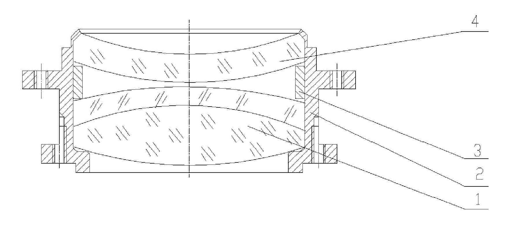
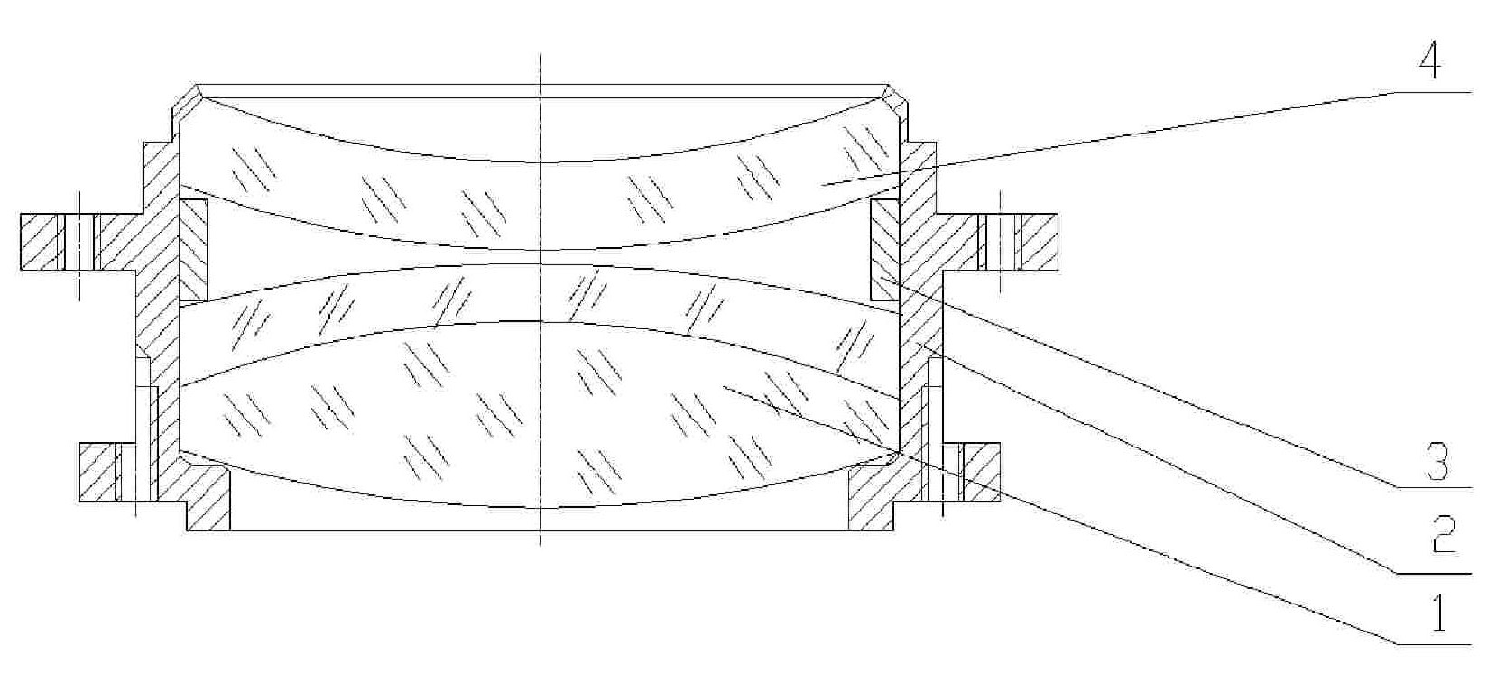
[0017] In the method for measuring optical parts provided by the present invention, the measured ambient temperature is 20°C ± 2°C. Taking the measurement of the distance between the centers of the optical part lens 4 and the cemented lens 1 as an example, the specific steps of the measuring method are as follows:

[0018] (1) Use a three-coordinate measuring machine to carry out physical measurement of the optical parts lens barrel 2, lens 4, cemented lens 1 and adjustment block 3 with the feature measurement method to obtain relevant data on the characteristics of each part thickness, length, curved surface, etc., which can also be used The method of scanning measurement is used for measurement;

[0019] (2) Carry out mathematical modeling to the above-mentioned optical parts under the three-dimensional modeling software SolidWorks software environment according to the measured part characteristic data, obtain the three-dimensional mathematical model of each part;

[0020] (...


PUM


Abstract

The invention relates to a method for measuring an optical part. The method comprises the following measuring steps: 1, measuring the characteristics of the optical part by using a three-dimensional digitizer; 2, according to the measured characteristic data of the optical part, establishing a three-dimensional mathematical model corresponding to each optical part by using three-dimensional modeling software; 3, carrying out entity assembling on the optical part to form an incomplete entity, and measuring the position relation of the optical part in the incomplete entity; 4, according to measured data of the position relation, carrying out virtual assembling on the established three-dimensional mathematical model of each optical part; 5, continuously assembling and measuring; 6, judging whether the virtually-assembled three-dimensional mathematical models of all the parts needed for measurement are obtained, if the virtually-assembled three-dimensional mathematical model of all the parts needed for measurement are not obtained, carrying out the step (5) till obtaining the virtually-assembled three-dimensional mathematical models of all the parts needed for measurement, and if so, carrying out the following step; and 7, obtaining the needed data of the optical part through measurement of the virtually-assembled three-dimensional mathematical model and / or calculation of relevantdimensions.

Description

technical field [0001] The invention relates to optical measurement technology, especially a measurement method for optical components. Background technique [0002] The measurement of the center distance of optical parts is often used in optical assembly. For optical systems with high precision requirements, in order to improve the assembly accuracy of the optical system and ensure the imaging quality of the optical system, it is necessary to inspect the assembly results of the optical parts. There are many methods for measuring the center distance of optical parts in a conventional coaxial optical system, but there are few methods for measuring the center distance of optical parts in a non-coaxial optical system with a certain spatial angle. There is an urgent need for a high-precision, operable strong measurement method. Contents of the invention [0003] The object of the present invention is to provide a measuring method for optical parts with high measuring accuracy...

Claims


Application Information

Patent Timeline
Patent Type & Authority Patents(China)
IPC IPC(8): G01B21/00G01B21/16G01B21/20G01B21/22G06T17/00
Inventor 王战胜
Owner LUOYANG INST OF ELECTRO OPTICAL EQUIP OF AVIC
Learn More