Backlight module and liquid crystal display

A liquid crystal display and backlight module technology, which is applied in the direction of instruments, optics, nonlinear optics, etc., can solve the problems of increased production man-hours, increased production costs, and reduced effects, and achieve the effect of improving yield

Inactive Publication Date: 2009-12-09
INNOLUX CORP
View PDF0 Cites 13 Cited by
  • Summary
  • Abstract
  • Description
  • Claims
  • Application Information

AI Technical Summary

Problems solved by technology

However, increasing the radius of the R corner will reduce the effect of the rubber frame 130 bearing against the lugs 122. In addition, increasing the number of lugs 122 will increase the production man-hours and indirectly cause an increase in production costs.

Method used


Image

  • Backlight module and liquid crystal display
  • Backlight module and liquid crystal display
  • Backlight module and liquid crystal display

Examples


Embodiment Construction

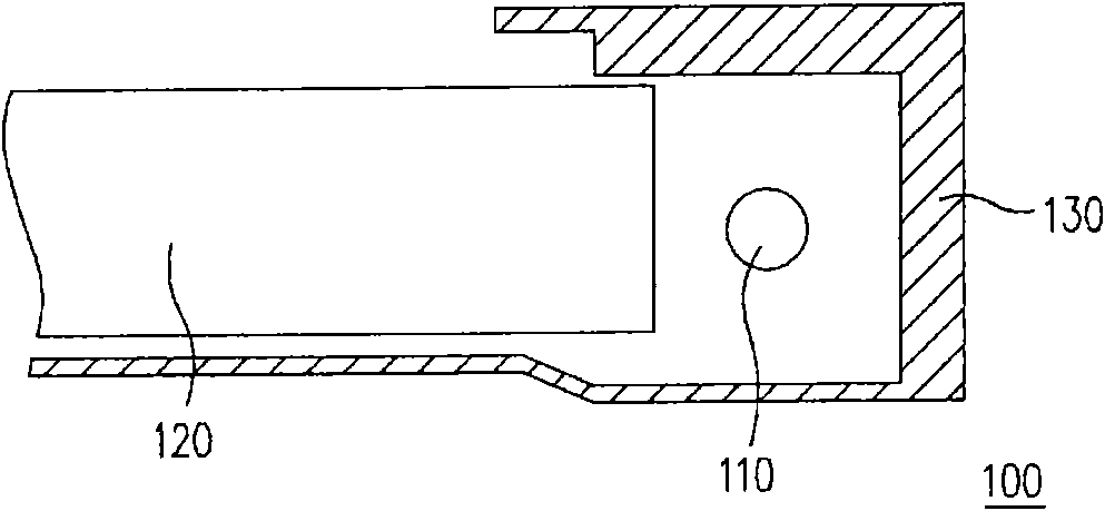
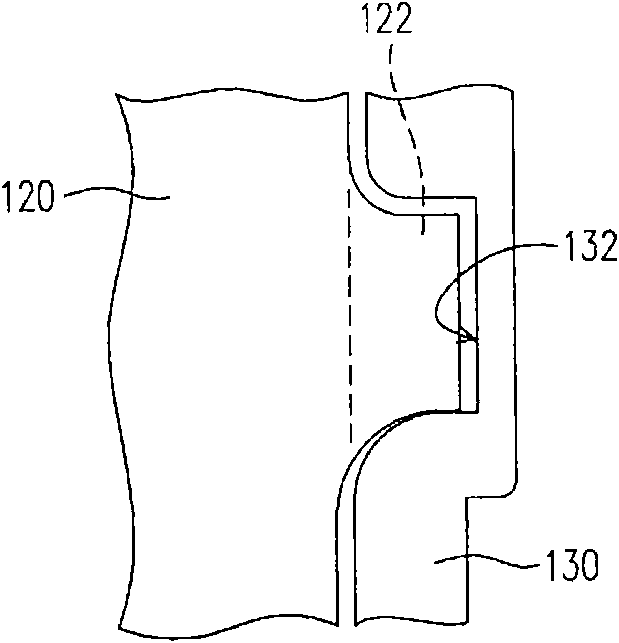
[0041] Figure 3A is a cross-sectional view of a backlight module according to an embodiment of the present invention, and Figure 3B for Figure 3A The top view partial enlarged view of the backlight module. Please also refer to Figure 3A and Figure 3B , the backlight module 200 includes an outer frame 210 , a light source 220 , a light guide plate 230 , a plastic frame 240 and a plurality of buffer structures 250 . In this embodiment, the material of the outer frame 210 is metal.

[0042] The light source 220, the light guide plate 230 and the plastic frame 240 are all configured in the outer frame 210, wherein the light source 220 is located on one side of the outer frame 210, and the light source 220 in this embodiment can be a cold cathode fluorescent lamp (CCFL) or a light emitting diode (LED). ). The light guide plate 230 is disposed beside the light source 220 , wherein the light guide plate 230 has a light guide plate body 232 and a plurality of lugs 234 , and...


PUM


Abstract

The invention discloses a backlight module and a liquid crystal display. The backlight module comprises an outer frame, a light source, a light guide plate, a glue frame and a plurality of buffer structures. The light source is arranged at one side in the outer frame; the light guide plate is arranged in the outer frame, positioned aside the light source and provided with a plurality of lugs, wherein the lugs are positioned at the two opposite sides of the light guide plate. The glue frame is arranged in the outer frame and positioned between the light guide plate and the light source, wherein the glue frame is provided with a plurality of recessed openings at a place corresponding to the lugs, and the recessed openings are suitable for bearing the lugs. In addition, the buffer structures are arranged on a bearing surface of the recessed openings of the glue frame. By the arrangement of the buffer structures, the backlight module has the preferential shock resistance effect.

Description

technical field [0001] The invention relates to a display, and in particular to a liquid crystal display with good impact test yield and a backlight module thereof. Background technique [0002] Whether it is a cathode ray tube display device or a liquid crystal display device, the backlight module needs to provide light to display images with sufficient brightness. Backlight modules can be classified into side-illuminated backlight modules and direct-lit backlight modules according to the location of the light source. [0003] Figure 1A is a cross-sectional view of a known side-illuminated backlight module, and Figure 1B for Figure 1A The top partial enlarged view of the light guide plate and the frame of the backlight module. like Figure 1A and Figure 1B As shown, in the side-illuminated backlight module 100 , a light guide plate 120 is usually provided beside the light source 110 to correct the light transmission direction of the light source 110 . In order to fa...

Claims


Application Information

Patent Timeline
Patent Type & Authority Applications(China)
IPC IPC(8): G02F1/13357G02F1/1333G02F1/1335
Inventor 林茂兴
Owner INNOLUX CORP
Why Eureka
Try Eureka