
Filter coefficient regulator and method thereof

A technology for filter coefficients and adjustment devices, applied in electromagnetic wave transmission systems, transmission systems, electromagnetic receivers, etc.

Active Publication Date: 2009-12-09
FUJITSU LTD
View PDF0 Cites 24 Cited by
  • Summary
  • Abstract
  • Description
  • Claims
  • Application Information

AI Technical Summary

Problems solved by technology

Although this avoids the convergence speed problem of DD, it cannot avoid the singularity problem of CMA

Method used


Image

  • Filter coefficient regulator and method thereof
  • Filter coefficient regulator and method thereof
  • Filter coefficient regulator and method thereof

Examples


Embodiment Construction

[0073] Embodiments of the present invention will be described in detail below in conjunction with the accompanying drawings.

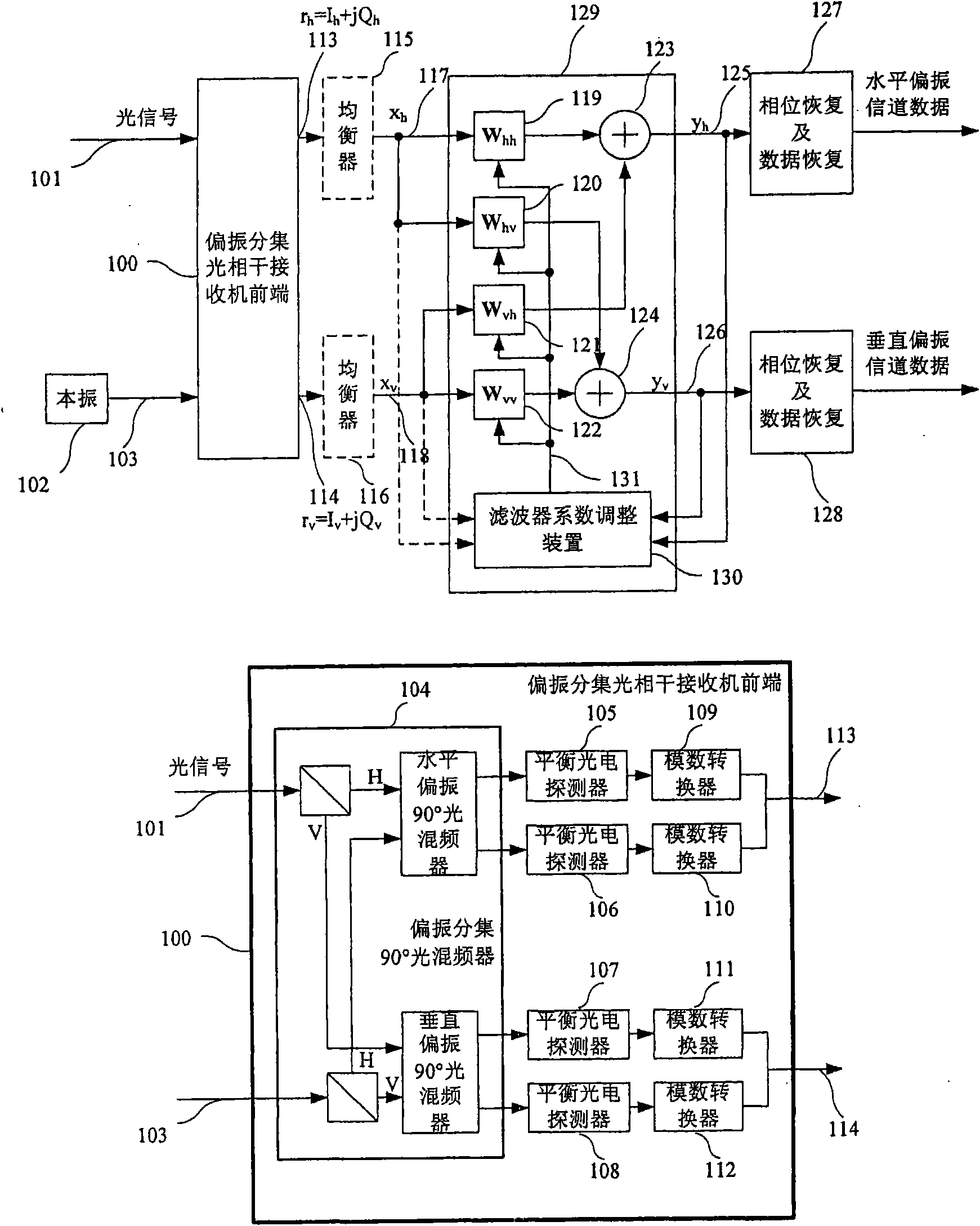
[0074] figure 1 A polarization-diversity coherent optical receiver that can adopt the device and method for adjusting filter coefficients of the present invention is shown.

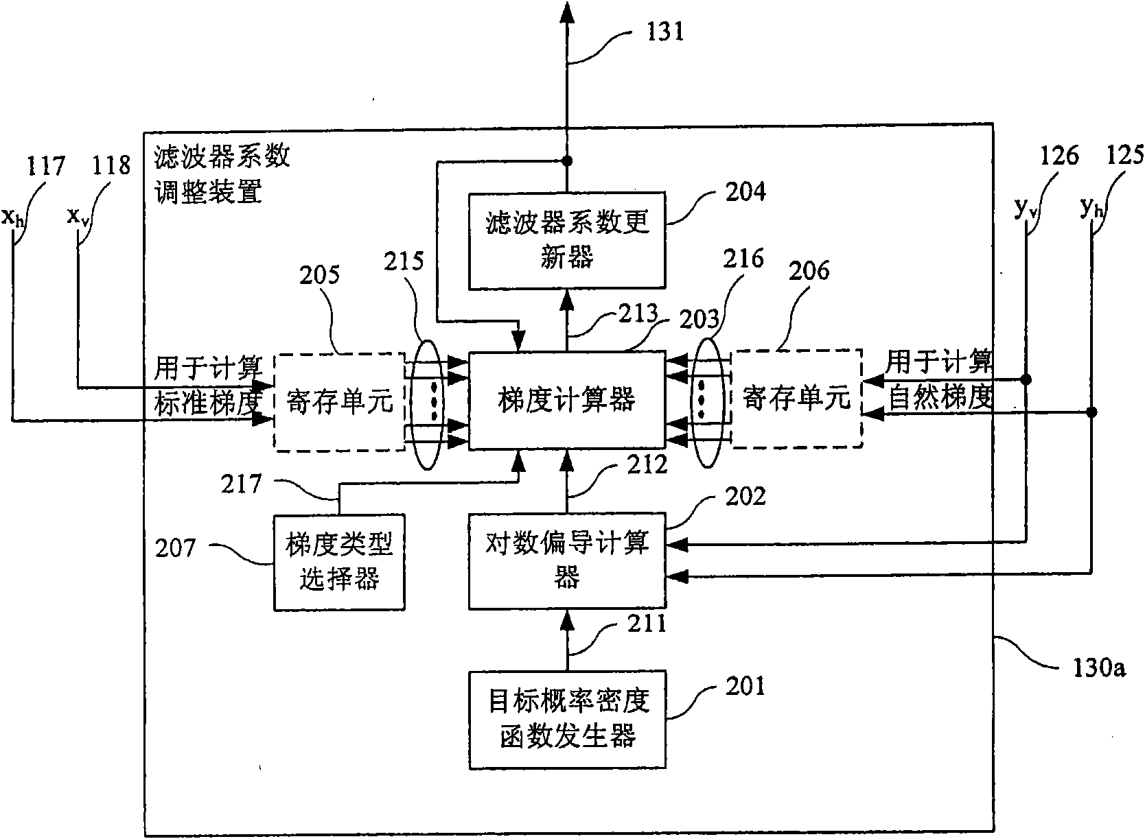
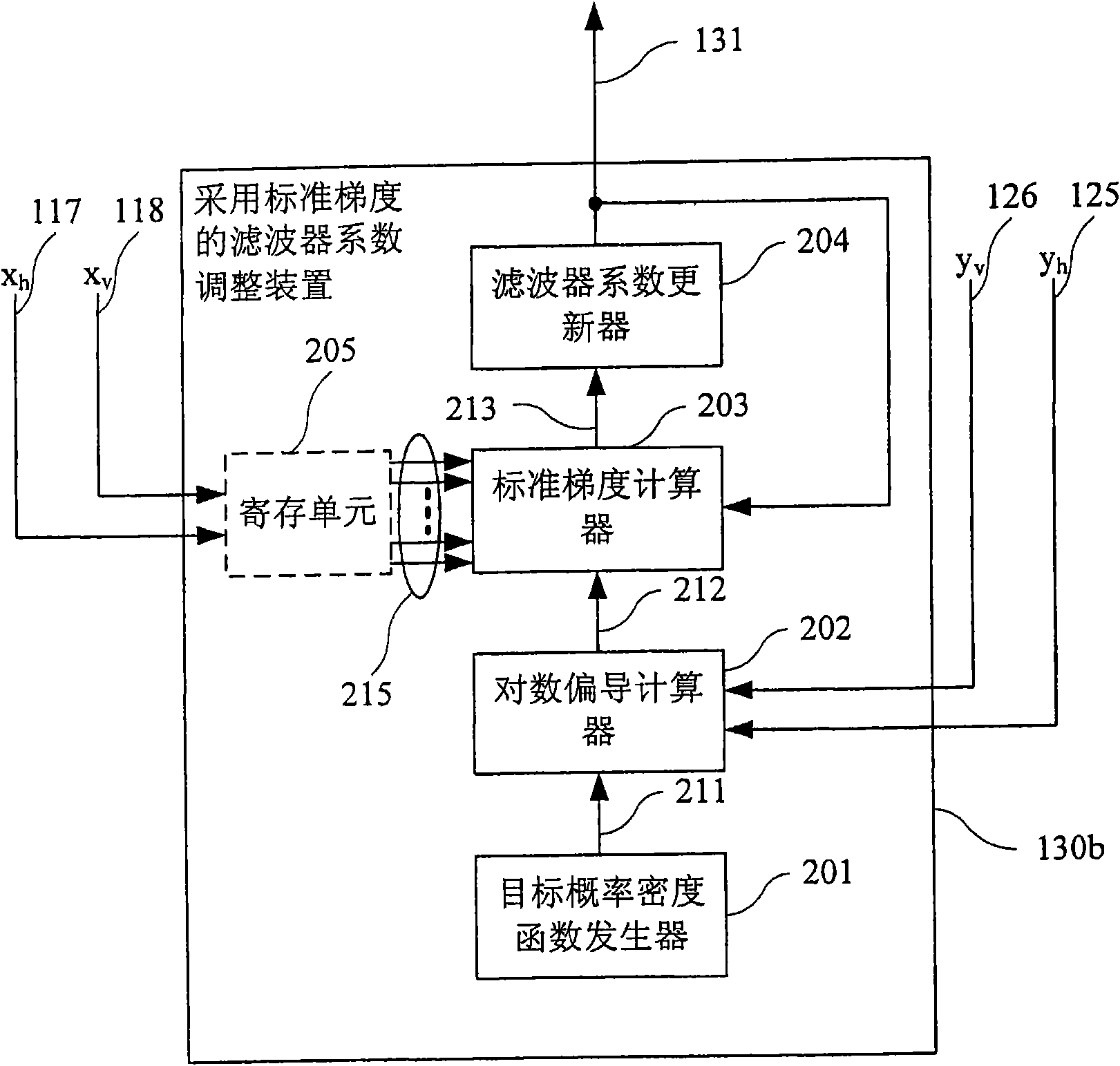
[0075] Such as figure 1As shown, four digital filters 119 - 122 (usually finite impulse response filters (FIR filters)), a filter coefficient adjustment device 130 and two adders 123 and 124 constitute a polarization demultiplexing device 129 . The input signal of the polarization demultiplexing device 129 may come from the output signals 113 and 114 of the front end 100 of the polarization diversity optical coherent receiver, or may be the output signal 113 equalized by the equalizer 115 and the output signal 114 by the equalizer 116 The equalized signal 118 . The purpose of the equalizers 115 and 116 is to preliminarily compensate transmission impairments such as dispersion, ...


PUM


Abstract

The invention relates to a filter coefficient regulator and a method thereof. The filter coefficient regulator is used in a polarization demodulation device which utilizes a filter to demodulate an input signal and obtain a demodulated output signal. The filter coefficient regulator is used for adjusting a filter coefficient and characterized by comprising a logarithm partial derivative calculating unit, a gradient calculating unit and a filter coefficient upgrading unit, wherein the logarithm partial derivative calculating unit is used for calculating a logarithm partial derivative value of an objective probability density function of the demodulated output signal when an independent variable is valued as the demodulated output signal; the gradient calculating unit is used for calculating the gradient of an objective optimization function for optimizing the distribution of the demodulated output signal according to the logarithm partial derivative value calculated by the logarithm partial derivative calculating unit; and the filter coefficient upgrading unit upgrades the filter coefficient according to the gradient calculated by the gradient calculating unit.

Description

technical field [0001] The present invention relates to a digital coherent optical receiver, more precisely, to a device and method for adjusting filter coefficients. Background technique [0002] The polarization multiplexing technology can double the spectrum utilization or capacity of the optical communication system by modulating different information on the two carrier lights with orthogonal polarization states in space. On the other hand, coherent detection technology can move the amplitude and phase information of two optical signals with orthogonal polarization directions to the baseband, so that all polarization information is preserved, which makes polarization demultiplexing using signal processing technology in the baseband digital domain become possible. [0003] Different from mobile communication, optical network needs to provide continuous and transparent transmission function for upper layer business. This requires that the signal processing function in th...

Claims


Application Information

Patent Timeline
Patent Type & Authority Applications(China)
IPC IPC(8): H04B10/148H04J14/06H04B10/516H04B10/00H04B10/61
CPCH04B10/611H04B10/614H04B10/6166H04J14/06H04B10/61H04B10/65
Inventor 张慧剑陶振宁谷村崇仁
Owner FUJITSU LTD
Learn More