Pneumatic tire

A technology for pneumatic tires and tires, which is applied in the direction of pneumatic tires, tire parts, tire treads/tread patterns, etc., can solve the problems of handling stability and quietness reduction, and achieve the purpose of suppressing the reduction of rigidity, improving grip, and suppressing Easy to clog effect

Inactive Publication Date: 2009-12-09
BRIDGESTONE CORP
View PDF2 Cites 8 Cited by
  • Summary
  • Abstract
  • Description
  • Claims
  • Application Information

AI Technical Summary

Problems solved by technology

[0005] However, in this pneumatic tire, the steering stability and quietness when running on a dry road may be reduced.

Method used


Image

  • Pneumatic tire
  • Pneumatic tire
  • Pneumatic tire

Examples


Embodiment Construction

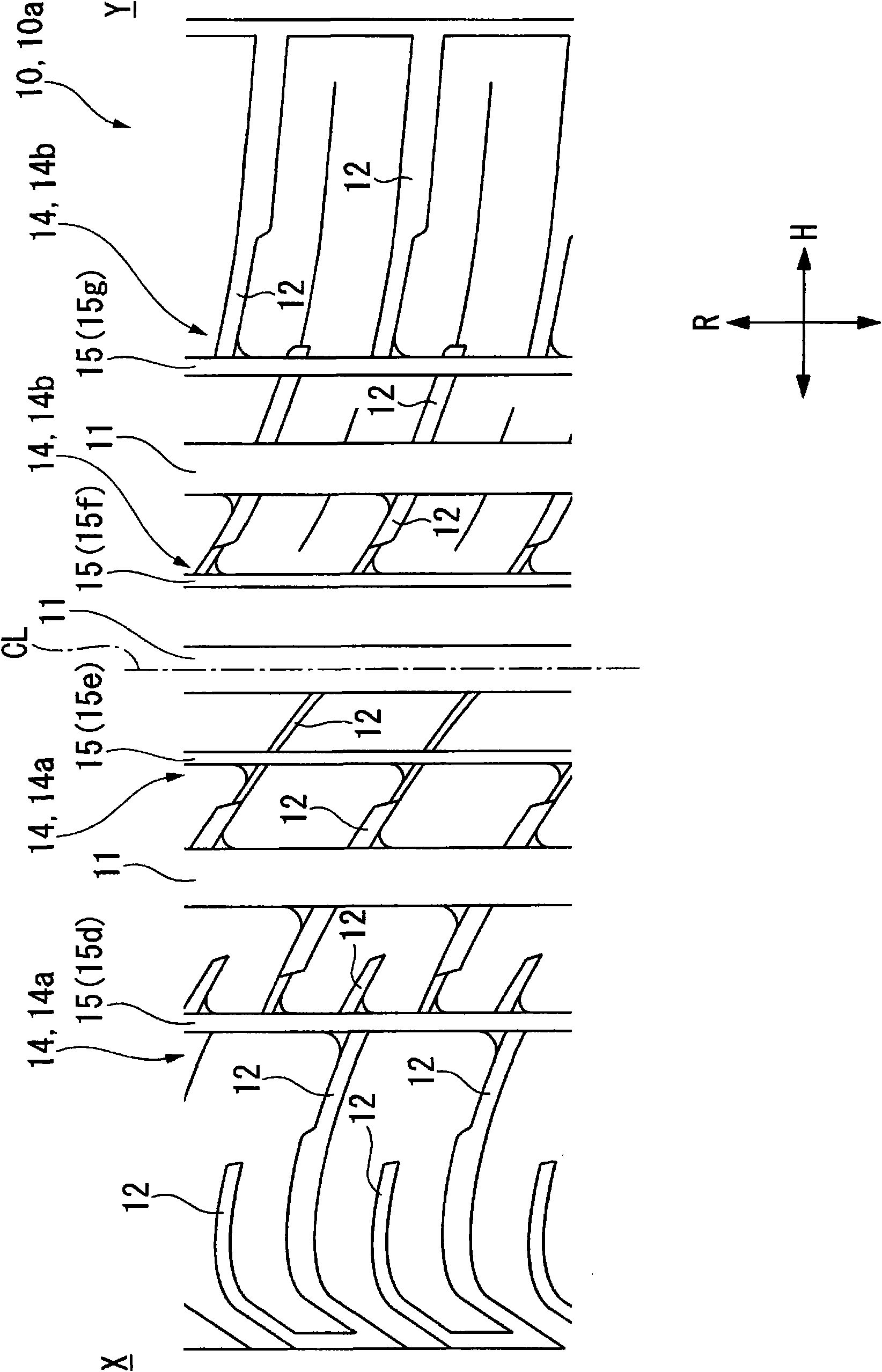
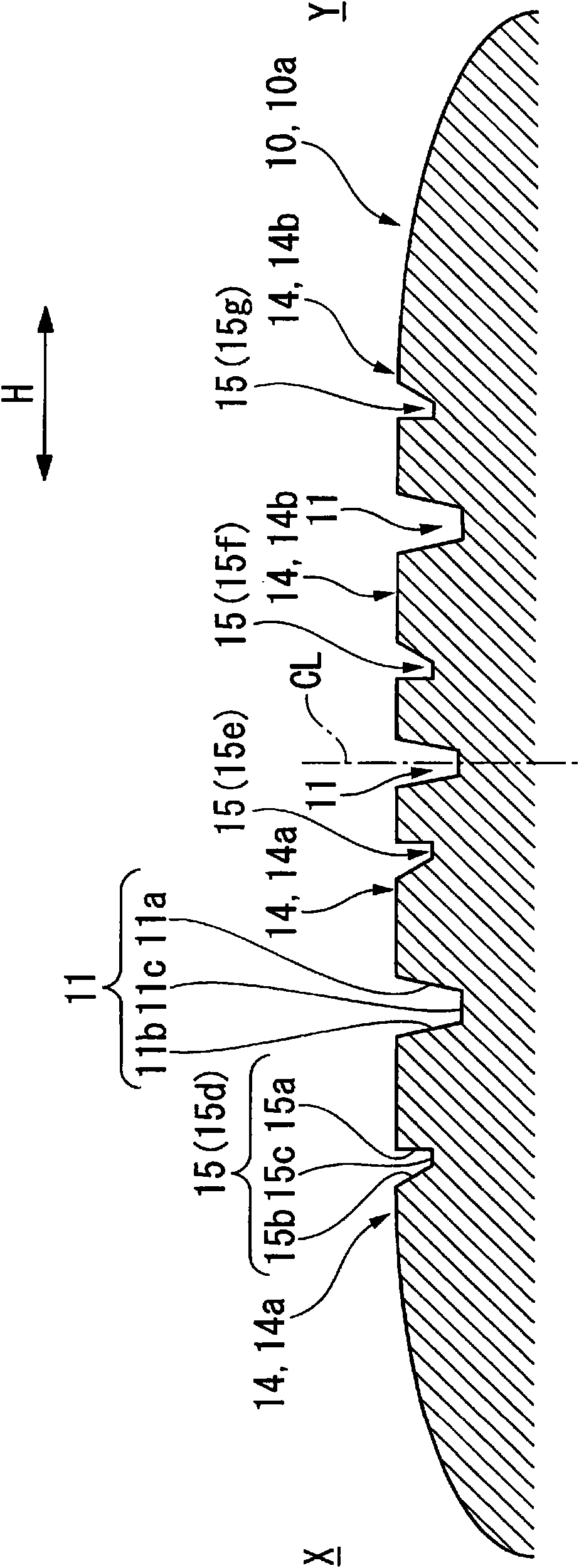
[0024] Below, refer to the attached Figure 1~3 One embodiment of the pneumatic tire of the present invention will be described. On the tread portion 10a of the pneumatic tire 10, a plurality of circumferential main grooves 11 extending in the tire circumferential direction R are formed at intervals in the tire width direction H, and a plurality of land portion rows 14 are defined by these circumferential main grooves 11. .

[0025] In the illustrated example, three circumferential main grooves 11 are formed, one of which is arranged so that its widthwise center is located on the tire equator CL, and the other two are arranged respectively from the tire equator CL to the vehicle outer side X and the vehicle inner side Y. Empty the positions at equal distances respectively. Accordingly, the plurality of land portion rows 14 are arranged at four positions separated from the tire equator portion CL on the tread portion 10a. Specifically, two of the four land portion rows 14 ar...


PUM


Abstract

A pneumatic tire 10 in which a plurality of circumferential main grooves 11 that extend in the tire circumferential direction are formed in a tread surface portion, and a plurality of land portion rows 14 are partitioned by the circumferential main grooves 11, in which in at least one of the plurality of the land portion rows 14a circumferential auxiliary groove 15 extending in the tire circumferential direction and having a narrower width and shallower depth than those of the circumferential main grooves 11 is formed in a position avoiding the tire centerline CL, and among both side faces 15a and 15b defining the circumferential auxiliary groove 15, one side face on the tire centerline side extends along the normal direction of the tread surface portion or is inclined to the tire centerline side by 5 DEG or less with respect to the normal direction, and the other side face on the side opposite to the tire centerline side is inclined to the side opposite to the tire centerline side by 10 DEG to 30 DEG with respect to the normal direction. In accordance with the present invention, it is possible to improve the turning performance on snowy roads without decreasing the steering stability or quietness during travel on a dry road surface.

Description

technical field [0001] The present invention relates to a pneumatic tire. [0002] This application claims priority based on Japanese Patent Application No. 2007-36266 filed on February 16, 2007 in Japan, and the content is incorporated herein. Background technique [0003] Conventionally, in order to improve running performance on icy and snowy roads, for example, various methods shown in Patent Document 1 below have been proposed. In recent years, in order to improve the turning performance of suppressing the side slip of the pneumatic tire when turning, among various running performances on ice and snow roads, studies have been made, for example, by increasing the width and depth of the circumferential main grooves formed on the upper part of the tread tread. The size or the number of strips is used to reduce the contact area of ​​the tread portion or to reduce the rigidity of the land portion rows formed on the tread portion. [0004] Patent Document 1: Japanese Patent...

Claims


Application Information

Patent Timeline
Patent Type & Authority Applications(China)
IPC IPC(8): B60C11/04B60C5/00B60C11/13
CPCB60C11/0309B60C11/12B60C11/1323B60C11/0306
Inventor 永井仁
Owner BRIDGESTONE CORP
Why Eureka
Try Eureka