Motor end cover as well as manufacture method and applied motor thereof

A technology for motor end caps and integrated circuits, which is applied in the manufacture of motor generators, electrical components, electromechanical devices, etc., can solve the problems of complex processing procedures, poor heat resistance, and low production efficiency, and achieve simple procedures and production efficiency. High, improve the effect of production efficiency

Active Publication Date: 2009-12-16
ZHONGSHAN BROAD OCEAN
View PDF0 Cites 14 Cited by
  • Summary
  • Abstract
  • Description
  • Claims
  • Application Information

AI Technical Summary

Problems solved by technology

[0002] At present, the general motor end cover is formed by stamping, stamping, and stretching of sheet metal parts. The bearing chamber and positioning spigot of the end cover need to be turned. The manufacturing cost of the cover is high, the weight is relatively heavy, the processing procedure is complicated, the production efficiency is low, the precision is not high, the stability is poor, and the heat resistance is not good

Method used


Image

  • Motor end cover as well as manufacture method and applied motor thereof
  • Motor end cover as well as manufacture method and applied motor thereof
  • Motor end cover as well as manufacture method and applied motor thereof

Examples


Embodiment 1

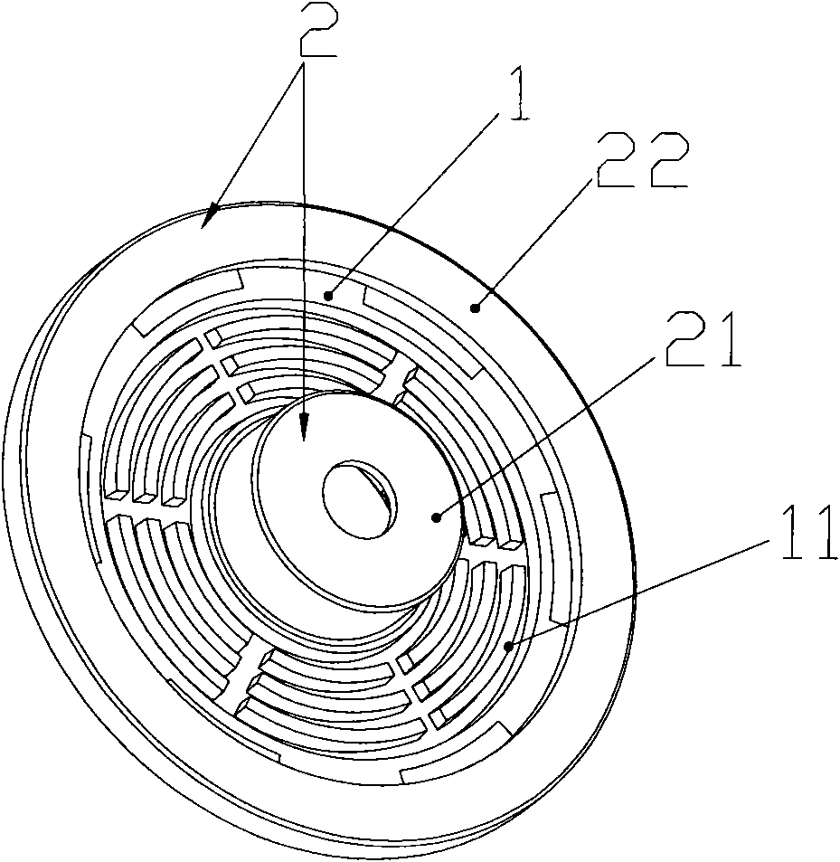
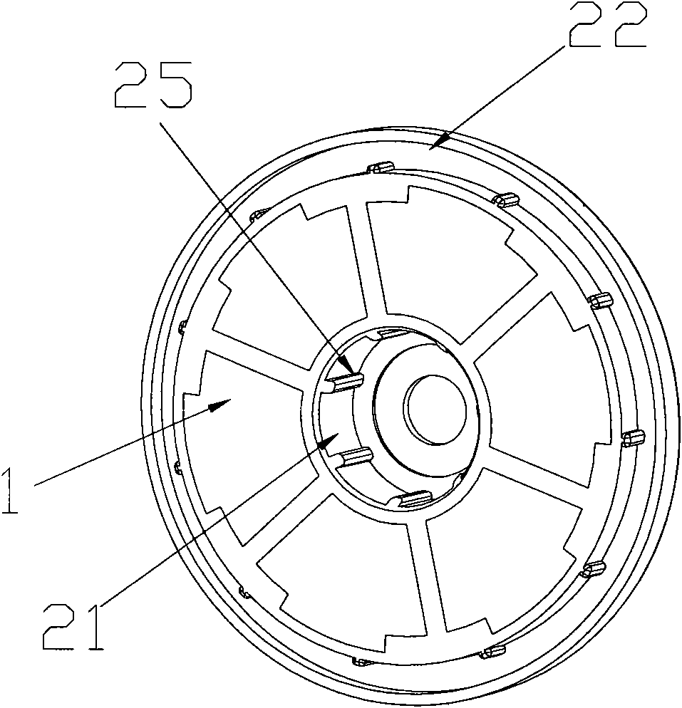
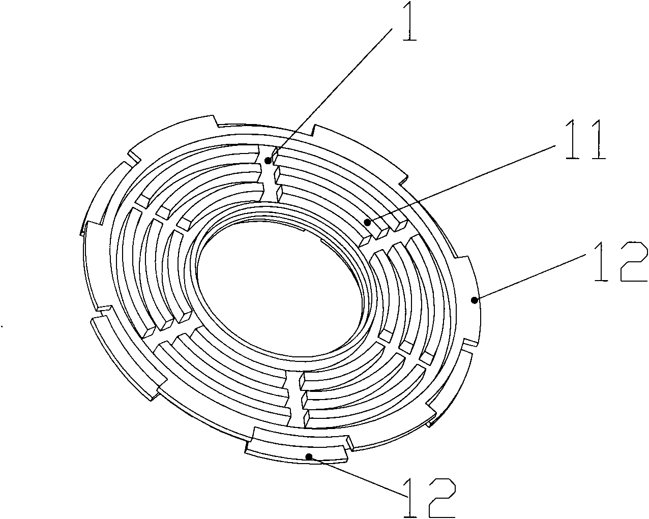
[0033] Such as figure 1 , figure 2 , image 3 , Figure 4 As shown, the present invention is composed of a metal heat sink 1 and an injection molded part 2, wherein the injection molded part 2 includes a bearing chamber 21 located in the center and a positioning notch 22 located on the periphery, and is embedded between the bearing chamber 21 and the positioning notch 22 The metal heat sink 1, the metal heat sink 1 is more suitable to be aluminum. The outer surface 12 of the metal heat sink 1 is provided with multiple rows of raised fins 11 , the inner surface of the metal heat sink 1 is flat, the fins 11 can be arc-shaped and radially distributed, and the fins 11 can increase the heat dissipation area. There are several blocks 12 protruding from the side of the metal heat sink 1, and the blocks 12 are embedded in the bearing chamber 21 and the positioning notch 22. The several blocks 12 protruding from the side can be divided into two rows according to the height, and the...

Embodiment 2

[0035] In the first embodiment, all gaps between the bearing chamber 21 and the positioning notch 22 are embedded with a whole metal heat sink 1 . However, in order to save costs and meet the heat dissipation requirements, a part of the gap between the bearing chamber 21 and the positioning notch 22 is embedded in the metal heat sink 1 , and the rest of the gap is sealed by injection molding to form a baffle 23 .

[0036] The manufacturing method of the motor end cover of the present invention is characterized in that the end cover is manufactured by injection molding process, and the metal radiator 1 is embedded in the injection molded part 2 during the injection molding process, so that it can be formed as a whole after injection molding. The motor of the present invention is equipped with a motor end cover at the end of the motor, and the motor end cover is composed of a metal heat sink 1 and an injection molded part 2, wherein the injection molded part includes a bearing ch...


PUM


Abstract

The invention relates to a motor end cover which comprises a metal heat dissipation piece (1) and an injection moulding piece (2), wherein the injection moulding piece comprises a bearing chamber (21) positioned at the center and a positioning clamp opening (22) positioned at the periphery; and the metal heat dissipation piece (1) is embedded between the bearing chamber (21) and the positioning clamp opening (22). The invention has the advantages of simple manufacture, lower cost, higher precision, light weight, high stability and easy heat dissipation.

Description

1. Technical field: [0001] The invention relates to a motor end cover, a manufacturing method of the motor end cover and a motor using the motor end cover. 2. Background technology: [0002] At present, the general motor end cover is formed by stamping, stamping, and stretching of sheet metal parts. The bearing chamber and positioning seam of the end cover need to be turned. The manufacturing cost of the cover is high, the weight is relatively heavy, the processing procedure is complicated, the production efficiency is low, the precision is not high, the stability is poor, and the heat resistance is not good. 3. Contents of the invention: [0003] The first object of the present invention is to provide a motor end cover, which is simple to manufacture, low in cost, high in precision, light in weight, good in stability and easy to dissipate heat. [0004] A motor end cover of the present invention is realized through the following technical solutions: [0005] A motor end...

Claims


Application Information

Patent Timeline
Patent Type & Authority Applications(China)
IPC IPC(8): H02K5/18H02K5/16H02K15/14
Inventor 鲁楚平
Owner ZHONGSHAN BROAD OCEAN
Why Eureka
Try Eureka