Cavity shallow foundation and construction method

A technology of shallow foundation and cavity, which is applied in the field of cavity shallow foundation and construction, can solve the problems of uneconomical, high cost, thick raft, etc., and achieve the effects of saving cost, reducing the amount of concrete, and saving costs

Inactive Publication Date: 2009-12-23
朱奎
View PDF0 Cites 8 Cited by
  • Summary
  • Abstract
  • Description
  • Claims
  • Application Information

AI Technical Summary

Problems solved by technology

[0002] For the foundation of mountainous buildings, deep foundation treatment and shallow foundation treatment are usually adopted. Deep foundation treatment usually adopts manual excavation pile foundation or mechanical drilled pile foundation, but the cost of deep foundation treatment is higher, while shallow foundation is deeper in the bearing layer. In some cases, the thickness of the raft is bound to be very thick, which is relatively uneconomical

Method used


Image

  • Cavity shallow foundation and construction method
  • Cavity shallow foundation and construction method

Examples


Embodiment 1

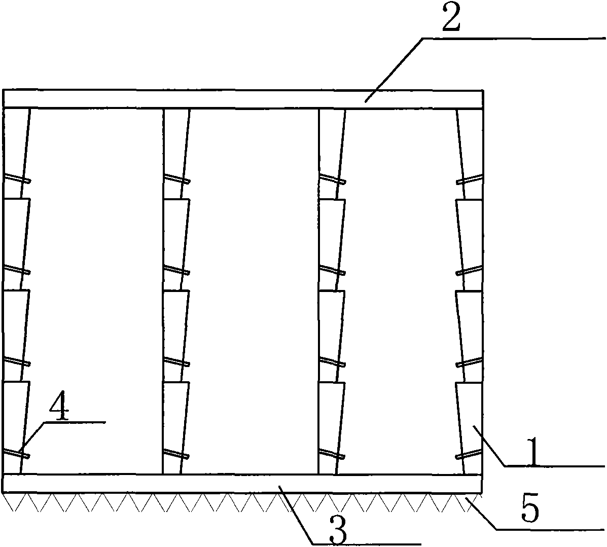
[0025] figure 1 It is a schematic diagram of a cavity shallow foundation, which includes a column 1 , a top plate 2 , a bottom plate 3 , and a drainage tube 4 .

[0026] Construction steps of the present invention include:

[0027] (1) Dig column 1 part soil.

[0028] The setting of the foundation column 1 corresponds to the span of the superstructure, and the spacing is 4.5m. Divide the foundation into three sections of column 1 according to the depth, and the height of each section of column 1 is 0.8.

[0029] (2) support pillar 1 formwork.

[0030] The thickness of the lower port of the column 1 is 80mm, and the thickness of the upper port is 150mm. The lap joint adopts a tongue-and-groove type, so that the upper and lower columns 1 are tightly lapped, and the inner wall is slightly inclined inward with a slope rate of 7%, which is convenient for formwork support. After each section of column 1 is dug down, the position of column 1 should be checked and corrected by usi...

Embodiment 2

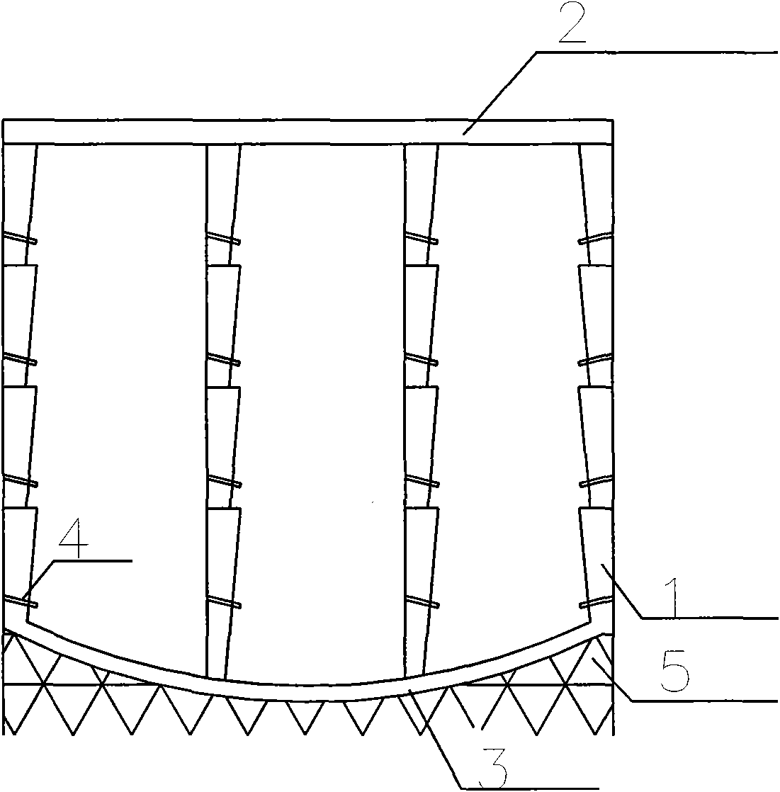
[0043] figure 2 It is a schematic diagram of cavity shallow foundation 2, which includes a column 1, a top plate 2, a bottom plate 3, and a drainage tube 4.

[0044] Construction steps of the present invention include:

[0045] (1) Dig column 1 part soil.

[0046] The setting of the foundation column 1 corresponds to the span of the superstructure, and the spacing is 4.5m. Divide the foundation into three sections of column 1 according to the depth, and the height of each section of column 1 is 0.8.

[0047] (2) support pillar 1 formwork.

[0048] The thickness of the lower port of the column 1 is 80mm, and the thickness of the upper port is 150mm. The lap joint adopts a tongue-and-groove type, so that the upper and lower columns 1 are tightly lapped, and the inner wall is slightly inclined inward with a slope rate of 7%, which is convenient for formwork support. After each section of column 1 is dug down, the position of column 1 should be checked and corrected by using ...


PUM


Abstract

The invention discloses a cavity shallow foundation and a construction method. The cavity shallow foundation comprises a top plate, an upright column, a bottom plate and a drainage pipe. The construction steps comprise the steps of: (1) digging the soil at the position of the upright column; (2) erecting an upright column template; (3) binding the reinforced steel bars of the upright column; (4) pouring upright column concrete; (5) excavating the earthwork in the foundation; (6) repeating the steps until to the bottom plate of the foundation; (7) binding the reinforced steel bar of the bottom plate of the foundation; (8) binding the concrete of the bottom plate of the foundation; and (9) taking a precast concrete or a cast-in-situ concrete as the seal of the top plate. The load-bearing upright column of the foundation is taken as a protection wall and leads the load-bearing structure to be connected with the protection wall into a whole, thereby greatly lowering the cost. Compared with the shallow foundation of a raft plate, the amount of in-built concrete of the cavity shallow foundation is significantly reduced; and compared with the foundation of a pile, the cost of the cavity shallow foundation can be saved by 30-40 percent.

Description

technical field [0001] The invention relates to building foundations, in particular to a cavity shallow foundation and a construction method. Background technique [0002] For the foundation of buildings in mountainous areas, deep foundation treatment and shallow foundation treatment are usually used. Deep foundation treatment usually adopts manual excavation pile foundation or mechanical drilled pile foundation, but the cost of deep foundation treatment is higher, while shallow foundation is deeper in the bearing layer. In some cases, the thickness of the raft is bound to be very thick, which is relatively uneconomical. However, if the middle of the thick raft can be hollowed out to form a box-shaped foundation, obviously the load-bearing performance of the foundation will be very good, and the economic benefits will also be significant. Contents of the invention [0003] Aiming at the deficiencies in the prior art, the object of the present invention is to provide a cav...

Claims


Application Information

Patent Timeline
Patent Type & Authority Applications(China)
IPC IPC(8): E02D27/00
Inventor 朱奎
Owner 朱奎
Why Eureka
Try Eureka