Rotary valve

A rotary valve and rotor technology, applied in the field of rotary valves, can solve the problems of large switching resistance, increasing the number and complexity of the inlet pipes, and increasing the complexity of the inlet pipes, so as to reduce the complexity and increase the switching frequency. Effect

Inactive Publication Date: 2011-03-30
LIHAN CRYOGENICS
View PDF0 Cites 1 Cited by
  • Summary
  • Abstract
  • Description
  • Claims
  • Application Information

AI Technical Summary

Problems solved by technology

[0004] However, the non-contact rotary valve in the prior art also has defects: the structure of the rotary valve has a large switching resistance when switching between high pressure and low pressure; in order to keep the balance and stability of the rotary valve in operation, the rotary valve uses two high-pressure intake The method of symmetrically setting the air inlet and two low-pressure air inlets increases the number and complexity of the air inlet pipes; when the rotation frequency of the motor itself is constant, increasing the switching frequency between high pressure and low pressure must rely on increasing the high pressure air inlet and the number of low-pressure inlets, which further increases the complexity of the inlet piping

Method used


Image

  • Rotary valve
  • Rotary valve
  • Rotary valve

Examples


Embodiment 2

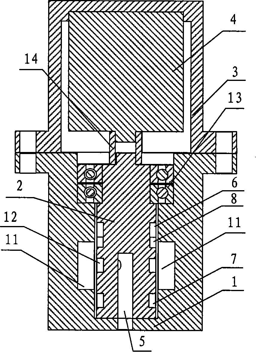
[0033] The difference between the second embodiment and the first embodiment is that the driving mechanism adopts an air motor instead of an electric motor. The air motor high-pressure inlet 16 and the air motor low-pressure outlet 17 are arranged on the sealing cover 3, the gas flows in from the air motor high-pressure inlet 16, flows through the air motor 14 to make the air motor 14 rotate, thereby driving the rotor 2 to rotate, and then flows from the air motor to the air motor at a low pressure. Exit 17 flows out. The high-pressure inlet 16 of the air motor is connected to the same high-pressure source as the high-pressure inlet 9, and the low-pressure outlet 17 of the air motor is connected to the same low-pressure source as the low-pressure inlet 10. The flow valve 18 is used to control the flow of air flowing into the air motor 14 , thereby adjusting the speed of the air motor 14 , and further controlling the switching frequency of the rotor 2 . Figure 8 for Figure ...


PUM


Abstract

The invention discloses a rotary valve, which comprises a stator, a rotor arranged in the stator, a driving mechanism for driving the rotor to rotate, and a sealing cover connected with the stator; a small gap exists between the stator and the rotor; a gas channel is arranged in the rotor; a high pressure gas buffer chamber and a low pressure gas buffer chamber are arranged in the circumferentialdirection of the rotor, and are respectively provided with a notch; the circumferential direction of the rotor is also provided with a groove communicated with the gas channel; and the stator is provided with a high pressure gas inlet communicated with the high pressure gas buffer chamber, a low pressure gas inlet communicated with the low pressure gas buffer chamber, and a gas trough communicated with the groove. The rotary valve can reduce the switching resistance between high pressure and low pressure in the rotary valve, improves switching efficiency, reduces the complexity of a rotary valve system, and has reliable operation, long service life and low noise.

Description

technical field [0001] The invention relates to the field of refrigerator manufacturing, in particular to a contactless rotary valve. Background technique [0002] In the regenerative refrigerator system, the rotary valve is used to switch between high pressure and low pressure in the gas flow channel to form the stable fluctuating pressure required for the refrigerator to work. The rotary valves in early refrigerators were contact rotary valves, often called planar rotary valves. Due to the need for sealing, the rotor end face of the planar rotary valve is in close contact with the stator, which will not only cause problems such as high motor power and large volume and mass of the rotary valve, but also cause wear and tear due to the mechanical contact between the rotor and the stator. , the worn-out particles will not only reduce the life of the rotary valve, but also enter the refrigerator with the airflow, affecting the performance of the refrigerator. [0003] The app...

Claims


Application Information

Patent Timeline
Patent Type & Authority Patents(China)
IPC IPC(8): F16K31/04F16K11/085F16K27/00F25B41/04F16K31/36F16K47/04
Inventor 吴张华姜琳李海冰戴巍罗二仓吴杰
Owner LIHAN CRYOGENICS
Why Eureka
Try Eureka