Magnetic fixed turning lamp

A technology of magnetic fixation and lamps, which is applied in the direction of light source fixation, lighting and heating equipment, portable lighting devices, etc., can solve the problems of difficulty in obtaining illuminance and reasonable projection angle, difficulty in unifying the two, and unclear illumination, etc., to achieve Labor-saving, easy to carry, and low-cost effects

A technology of magnetic fixation and lamps, which is applied in the direction of light source fixation, lighting and heating equipment, portable lighting devices, etc., can solve the problems of difficulty in obtaining illuminance and reasonable projection angle, difficulty in unifying the two, and unclear illumination, etc., to achieve Labor-saving, easy to carry, and low-cost effects

CN101608740AInactive Publication Date: 2009-12-23OCEANS KING LIGHTING SCI&TECH CO LTD

Image

  • Magnetic fixed turning lamp
  • Magnetic fixed turning lamp
  • Magnetic fixed turning lamp

Examples


Embodiment Construction

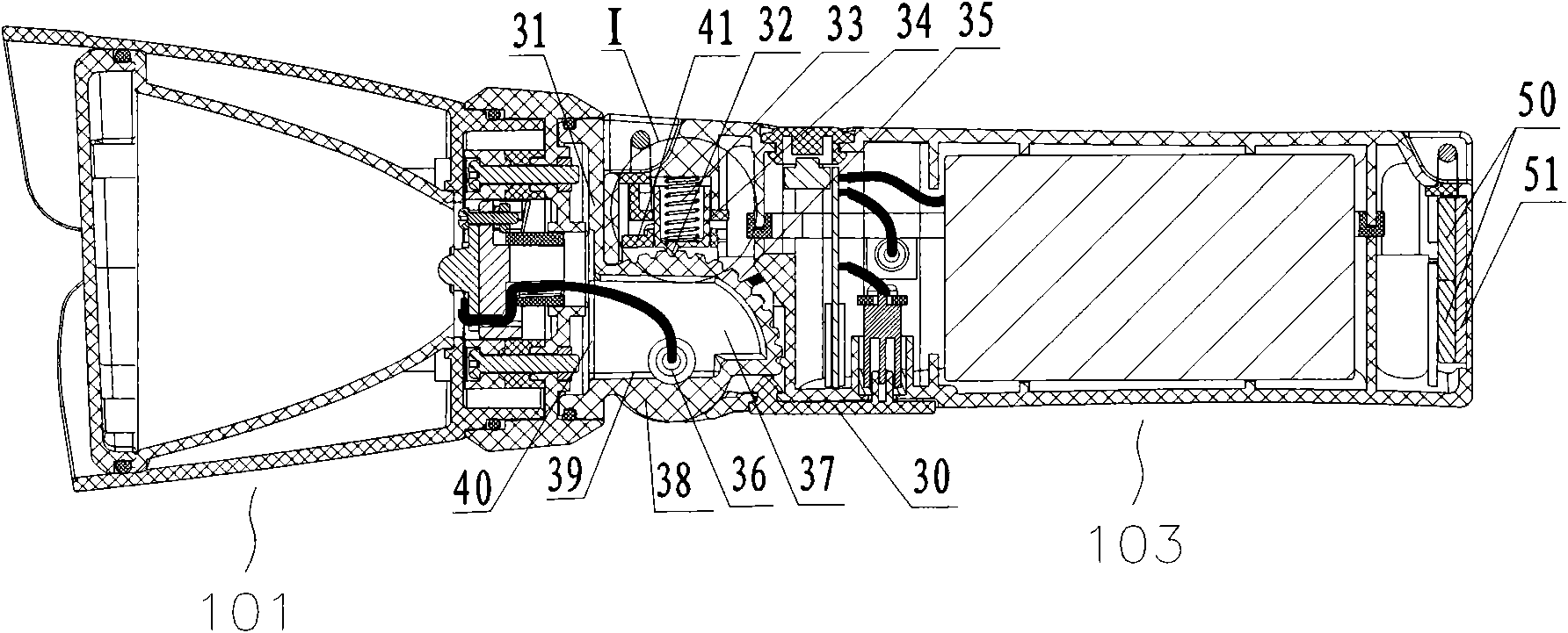
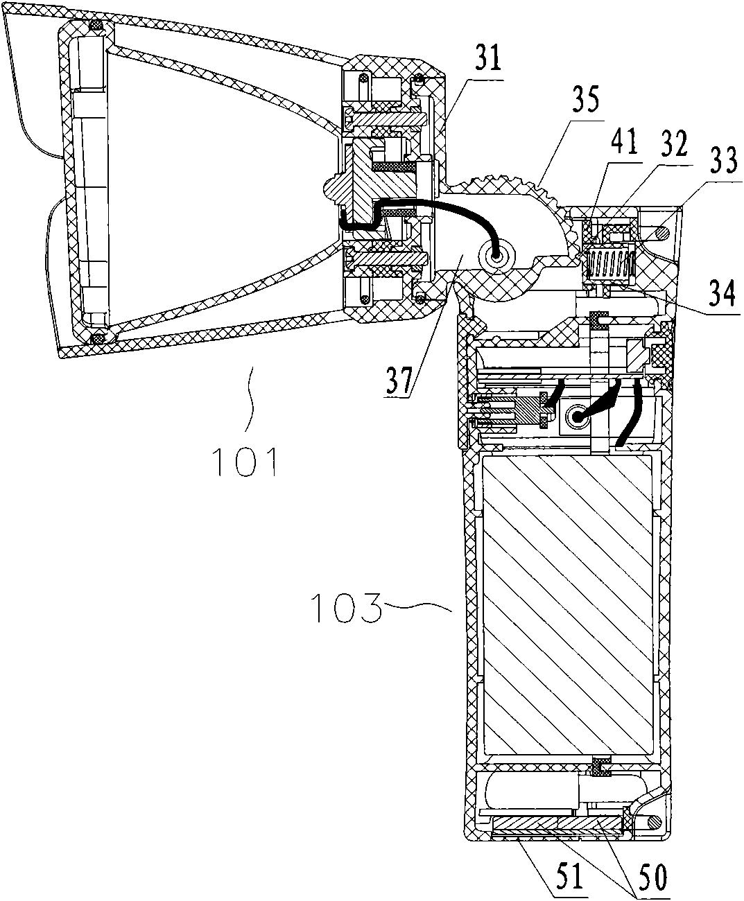
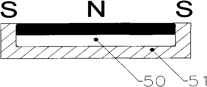
[0025] like figure 1 , 2 As shown in , 3, a magnetically fixed steering lamp includes a lamp head 101 and a lamp body 103, wherein the lamp body 103 includes a non-metal lamp body shell 30, and a steering device is provided between the lamp head 101 and the lamp body 103, and the steering The device changes the relative position of the lamp head 101 and the lamp body 103 , and adjusts the irradiation direction of the lamp head 101 . A magnetic adsorption device is provided in the rear of the lamp body shell, and the magnetic adsorption device can also be arranged at other positions in the lamp body shell, for example: the side surface of the lamp body shell 30 . An embodiment of the magnetic adsorption device includes a permanent magnet 50 , and a U-shaped magnetic conducting body 51 is wrapped around the permanent magnet 50 , and the permanent magnet 50 is flush with the outer edge and the top surface of the magnet conducting body 51 .

[0026] like Figure 4 As shown, ano...


PUM


Abstract

The invention discloses a magnetic fixed turning lamp, which comprises a lamp body and a lamp holder, wherein the lamp body comprises a lamp body shell made of nonmetal; a turning device used for adjusting the irradiating direction of the lamp holder is arranged between the lamp holder and the lamp body; and the lamp body shell is internally provided with a magnetic absorbing device. The invention provides the magnetic fixed turning lamp, which has the advantages of simple structure, reliable working, labor conservation and portability, can absorb the lamp on an adjacent iron object anytime and anywhere and can flexibly turn the irradiating direction of the lamp holder.

Description

technical field [0001] The invention relates to a portable lamp, in particular to a magnetically fixed steering lamp. Background technique [0002] Portable lighting fixtures are mainly used in some occasions that need to be moved. At present, the commonly used portable lighting fixtures are mostly portable, open-clamped and hanging types. These portable lighting fixtures have some deficiencies in use; the portable lighting fixtures need to be hand-held by the operator or hand-held by a special person to work together, which is a waste of manpower. Especially when working in a place where only one person can operate in a small space, it is very inconvenient to hold the lamp while working, and it may not be able to illuminate the required position or the distance is too far to illuminate. Clamp-on or hanging-type lighting fixtures are difficult to obtain high illuminance and reasonable projection angle due to working conditions. In addition, in use, the irradiation position...

Claims


Application Information

Patent Timeline
23 Dec 2009
Publication
CN101608740A
IPC
F21L4/00; F21V21/096; F21V14/02
Inventors
周明杰; 罗志祥