Fish grass feeding device for aquaculture

An aquaculture, fish grass technology, applied in fish farming, circuit devices, battery circuit devices, etc., can solve the problems of labor consumption and low efficiency

Pending Publication Date: 2021-04-30
安徽省黄雀畈现代农业开发有限公司
View PDF28 Cites 0 Cited by
  • Summary
  • Abstract
  • Description
  • Claims
  • Application Information

AI Technical Summary

Problems solved by technology

[0005] The purpose of the present invention is to solve the problems of labor-intensive and low efficiency in the prior art, and propose a fish and grass feeding device for aquaculture

Method used


Image

  • Fish grass feeding device for aquaculture
  • Fish grass feeding device for aquaculture
  • Fish grass feeding device for aquaculture

Examples


Embodiment 1

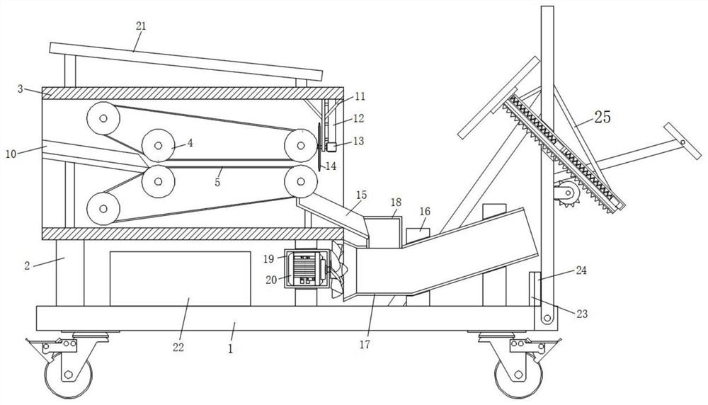
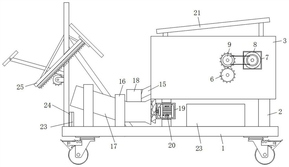
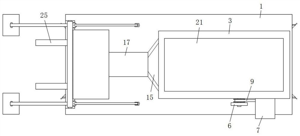
[0034] refer to Figure 1-7, a fish and grass feeding device for aquaculture, comprising a base 1, universal wheels are fixedly installed at the four corners of the bottom surface of the base 1, a fixed column 2 is welded on one side of the top surface of the base 1, and the top surface of the fixed column 2 is passed through a screw A crushing barrel 3 is fixedly connected, and the inner wall of the crushing barrel 3 is rotatably equipped with a pulley 4, and the three pulleys 4 in the same group are fixedly connected with a conveyor belt 5, and the two input ends of the conveyor belt 5 pass through the front side wall of the crushing barrel 3 And through the gear set 6 rotation connection, one side of the front end of the crushing bucket 3 is also fixed with a sealed box 7, the inner wall of the front end of the sealed box 7 is fixedly connected with a servo motor 8 by screws, and the output end of the servo motor 8 is connected to the The input end of one conveyor belt 5 is...

Embodiment 2

[0037] like Figure 4-7 As shown, this embodiment is basically the same as Embodiment 1. Preferably, the fixing assembly 2516 includes a fixing plate 2516a, the bottom surface of the fixing plate 2516a is fixedly connected with fixing pins 2516b, and a plurality of fixing pins 2516b are arranged and distributed in a matrix in the fixing plate 2516a bottom surface.

[0038] In this embodiment, the bottom end of the support rod 2515 is fixedly connected with a fixing component 2516, thereby facilitating the temporary fixing of the toggle mechanism 25, thereby ensuring a more stable operation of the toggle mechanism 25, and providing a certain guarantee for the stable feeding of fish and grass.

Embodiment 3

[0040] like Figure 1-3 As shown, this embodiment is basically the same as Embodiment 1. Preferably, the output end of the solar panel 21 is electrically connected to the input end of the battery pack 22, and the servo motor 1 8, the servo motor 2 13 and the biaxial motor 2510 The power supply ends are electrically connected to the output end of the battery pack 22 through wires.

[0041] In this embodiment, the solar panel 21 absorbs solar energy and stores it in the storage battery pack 22, so as to realize the collection of energy. The output end of the device is electrically connected, so as to meet the use of the device in remote areas, and greatly enhance the flexibility of the use of the device.


PUM


Abstract

The invention discloses a fish grass feeding device for aquaculture. The fish grass feeding device comprises a base, universal wheels are fixedly installed at the four corners of the bottom surface of the base, a fixing column is welded to one side of the top surface of the base, a smashing barrel is fixedly connected to the top surface of the fixing column through screws, belt wheels are rotatably installed on the inner wall of the smashing barrel, conveyor belts are fixedly connected among the three belt wheels in the same set, the input ends of the two conveyor belts penetrate through the front side wall of the smashing barrel and are rotationally connected through a gear set, a first sealing box is further fixed to one side of the front end surface of the smashing barrel, a first servo motor is fixedly connected to the inner wall of the front end of the first sealing box through screws, and the output end of the first servo motor is rotationally connected with the input end of one conveyor belt through a belt. The fish grass feeding device is reasonable in design and stable in operation, automatic feeding and stirring operation of fish grass can be achieved in the using process, and therefore automatic movement of the fish grass is achieved, fries in the middle of a pond can quickly find food, and the fish grass feeding efficiency is greatly improved.

Description

technical field [0001] The invention relates to the technical field of aquaculture equipment, in particular to a fish and grass feeding device for aquaculture. Background technique [0002] Aquaculture is the production activity of breeding, cultivating and harvesting aquatic animals and plants under human control. It generally includes the whole process of growing aquatic products from seedlings under artificial breeding management. In a broad sense, it can also include the proliferation of aquatic resources. [0003] After retrieval, the patent application number 201810145221.6 discloses a pasture crushing device for aquaculture, including a bottom plate, outriggers, box body, lower hopper, support rod, frame body, discharge hopper, crushing device and blowing device, the top of the bottom plate There are two outriggers installed on the left, a box is installed on the top of the two outriggers, a lower hopper is installed on the top of the box, and the lower hopper is conn...

Claims


Application Information

Patent Timeline
Patent Type & Authority Applications(China)
IPC IPC(8): A01K61/80H02J7/35
CPCA01K61/80H02J7/35Y02P60/60Y02A40/81
Inventor 侯长旺宋泽君冯江华
Owner 安徽省黄雀畈现代农业开发有限公司
Why Eureka
Try Eureka