
Marking machine

A marking machine and marking unit technology, applied in the field of marking machines, can solve the problems of increasing labor costs, reducing work efficiency, time-consuming and laborious, etc., and achieve the effects of simple structure, improved production efficiency, and convenient operation

Active Publication Date: 2013-04-17
XINGUANG NUMERICAL CONTROL TECH
View PDF8 Cites 22 Cited by
  • Summary
  • Abstract
  • Description
  • Claims
  • Application Information

AI Technical Summary

Problems solved by technology

The marking machine in the prior art needs to carry the gas cylinders manually, which is time-consuming and labor-intensive, which greatly increases the labor cost and reduces the work efficiency.

Method used


Image

  • Marking machine
  • Marking machine
  • Marking machine

Examples


Embodiment Construction

[0028] The specific implementation manner of the present invention will be described below in conjunction with the accompanying drawings.

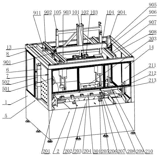
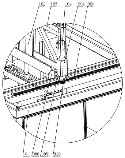
[0029] Such as figure 1 As shown, the marking machine includes a bed 1, on which a feeding unit 2, a fixing unit 3, and a discharging unit 4 are sequentially installed, and a marking unit 5 and a control panel 6 are also arranged on one side of the bed 1 ; Install column 7 around bed 1, also install transparent safety cover 14 between each column 7. A frame 8 is installed on the column 7, and the frame 8 is rectangular, and a wire groove 13 and a walking unit 9 are also installed on the frame 8, and a lifting translation unit 10 is installed on the walking unit 9, and the lifting translation unit 10 is connected to the clamping unit 12;

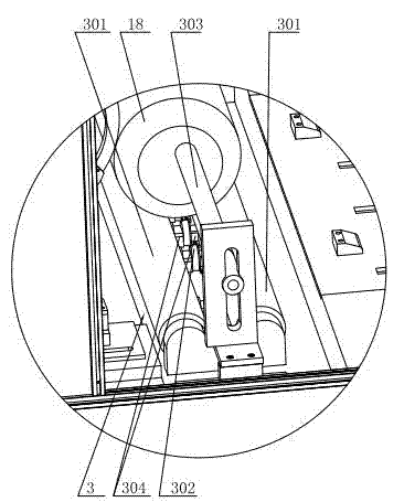
[0030] Such as figure 1 , Figure 4 As shown, the feed unit 2 and the discharge unit 4 both include a conveying plate 203, and on the bed 1, a cylinder is arranged at the bottom of the conveying plate ...


PUM


Abstract

The invention relates to a marking machine. The marking machine comprises a bed body, wherein a feeding unit, a fixing unit and a discharging unit are sequentially arranged on the bed body, and a marking unit and a control panel are further arranged at one side of the bed body; and upright posts are arranged at the periphery of the bed body, a frame is arranged on the upright posts, a walking unit is arranged on the frame, and a lifting translation unit is arranged on the walking unit and is connected with a clamping unit. According to the marking machine, the structure is simple, the operation is convenient, the full-automatic operations such as automatic feeding, marking and automatic discharging of an air bottle are realized, the stability of air bottle grabbing is realized by using pincers, the safety and the convenience can be realized, the automation degree is high, the tedious process that the air bottle requires to be manually carried in the prior art is avoided, the time and the labor are saved, not only is the cost saved, and but also the production efficiency is improved.

Description

technical field [0001] The invention relates to marking equipment, in particular to a marking machine. Background technique [0002] Pneumatic marking machine is an electromechanical integration equipment used for metal products. The computer controls the printing needle to move according to a certain trajectory in the Y and X two-dimensional planes. At the same time, the printing needle performs high-frequency impact movement under the action of compressed air. The corresponding marks are printed on the workpiece. The marking machine in the prior art needs to carry the gas cylinders manually, which takes time and effort, greatly increases the labor cost, and reduces the work efficiency. Contents of the invention [0003] Aiming at the above-mentioned existing problems, the applicant has carried out research and improvement, and provides a pneumatic marking machine with simple structure and convenient operation, which can realize the whole process of automatic entry, mark...

Claims


Application Information

Patent Timeline
Patent Type & Authority Applications(China)
IPC IPC(8): B41J2/22B41J3/407
Inventor 俞晓
Owner XINGUANG NUMERICAL CONTROL TECH
Learn More