
Swing cloth hopper device of airflow dyeing machine

An airflow dyeing machine and stencil technology, which is applied in textile processing machine accessories, textile material processing, textile material processing equipment configuration, etc., can solve the problems of cloth pressing, affecting air circulation, blocking cloth, etc.

Active Publication Date: 2013-05-29
WUXI DONGBAO MACHINERY MFG
View PDF4 Cites 0 Cited by
  • Summary
  • Abstract
  • Description
  • Claims
  • Application Information

AI Technical Summary

Problems solved by technology

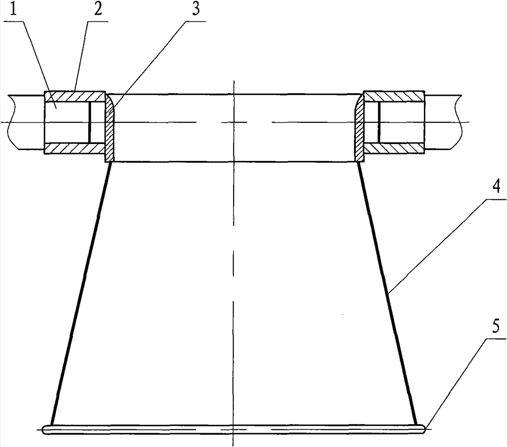
The disadvantage of this mechanism is that because the left and right buckets 4 are narrow at the top and wide at the bottom, the spreading of the cloth is relatively open, and it is easy to cause the phenomenon of cloth pressing during the stacking process, resulting in cloth blocking during the dyeing process.
If limit the width of left and right bucket 4 bottoms, can influence the circulation of air again

Method used


Image

  • Swing cloth hopper device of airflow dyeing machine
  • Swing cloth hopper device of airflow dyeing machine
  • Swing cloth hopper device of airflow dyeing machine

Examples


Embodiment Construction

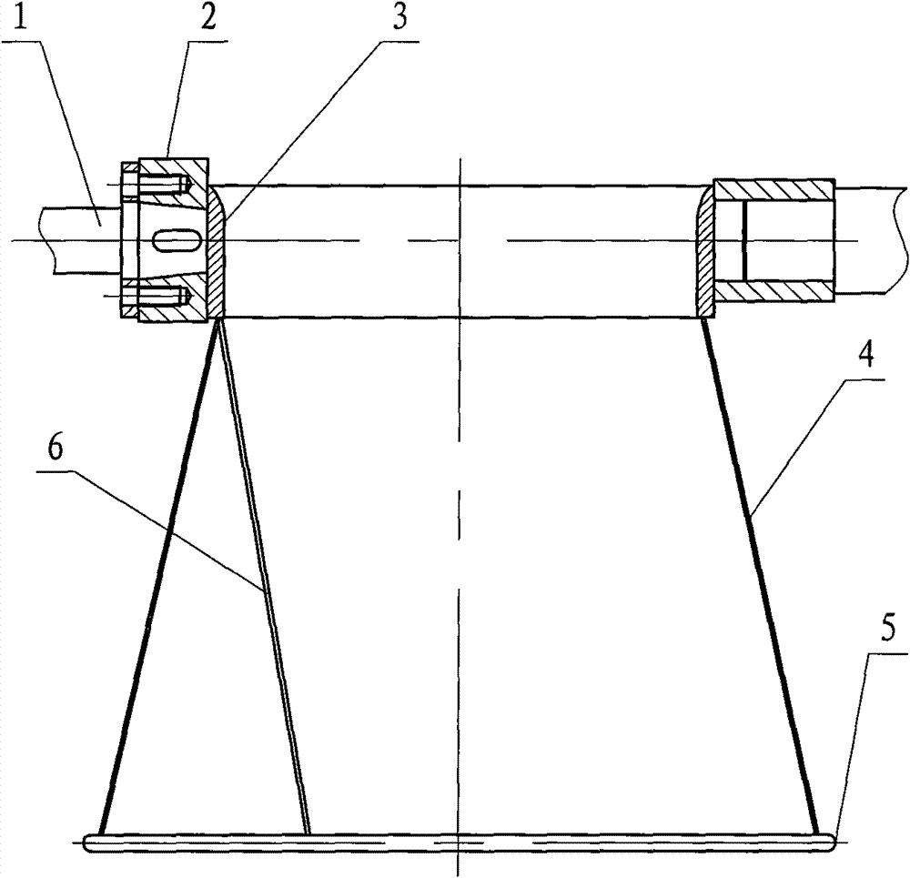
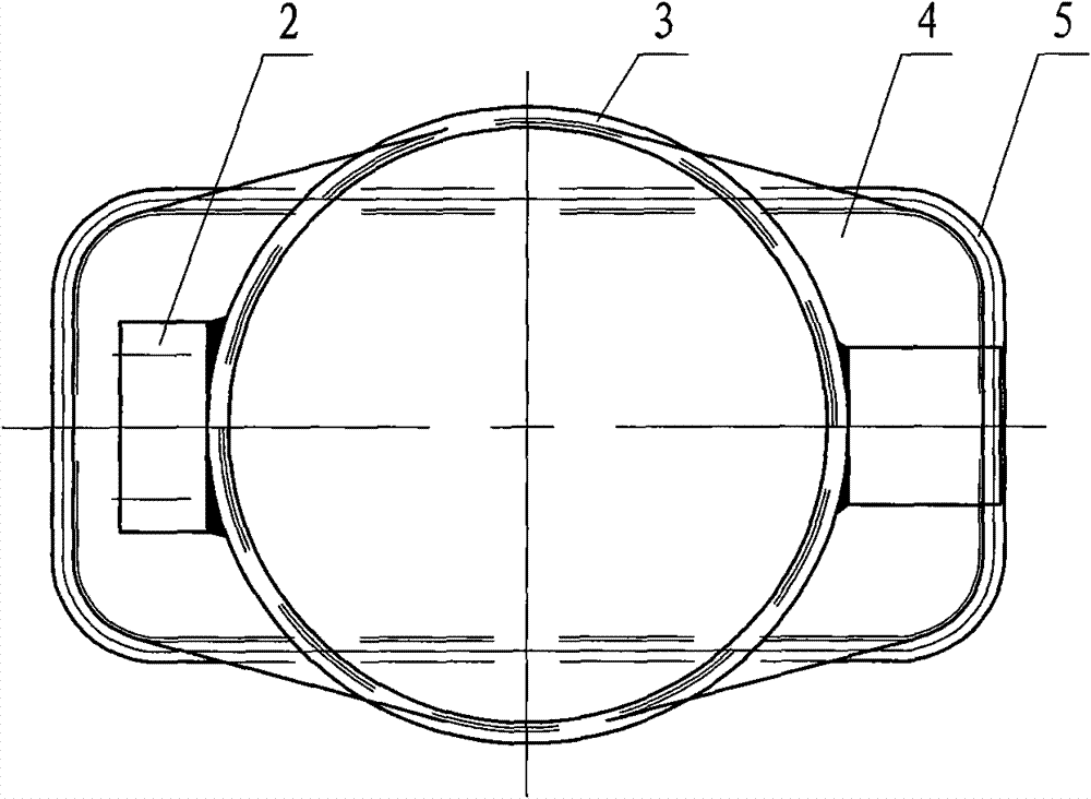
[0012] Such as figure 2 , image 3 As shown, the present invention includes an inner sleeve 3 and a swing bucket 4. The top of the left and right bucket 4 is circular, and the bottom is rectangular. The inner connecting sleeve 3 is in the shape of a circular tube, and an axle sleeve 2 is arranged on its side wall, and a linkage mechanism shaft 1 is installed in the axle sleeve 2, and a linkage mechanism is installed on the linkage mechanism axis 1. The improvement of the present invention lies in that a net plate 6 with ventilation holes 7 is arranged in the swing bucket, the top edge of the net plate 6 is connected with the top of the swing bucket 4, and the side of the net plate 6 is connected with the side of the swing bucket 4. The walls are connected, and the bottom edge of the screen plate 6 is parallel to the short side of the bottom rectangle of the left and right buckets 4.

[0013] Such as Figure 4 As shown, the ventilation holes 7 on the screen 6 are arranged ...


PUM


Abstract

The invention relates to a swing cloth hopper device of an airflow dyeing machine, which comprises an internal connecting sleeve and a swing cloth hopper; the top of the swing cloth hopper is circular, while the bottom is rectangular; the top of the swing cloth hopper is connected with the internal connecting sleeve; the inside of the swing cloth hopper is provided with a screen plate with vents;the top edge of the screen plate is connected with the top of the swing cloth hopper; the side edge of the screen plate is connected with the side wall of the swing cloth hopper; and the bottom edge of the screen plate is parallel to a short edge of a rectangle on the bottom of the swing cloth hopper. The screen plate is arranged in the swing cloth hopper to limit the tension width, so that the cloth is orderly placed and the cloth stacking phenomenon is not generated; and the screen plate is provided with the vents so as not to influence the ventilation.

Description

(1) Technical field [0001] The invention relates to a component used for an air-flow dyeing machine, in particular to a swing bucket device of the air-flow dyeing machine. (2) Background technology [0002] The air atomization dyeing machine adopts the principle of aerodynamics to inject the mixed air generated by the fan into the nozzle of the dyeing machine to drive the fabric to run. During the dyeing process, the airflow generated by the fan enters the nozzle and meets the dye liquor delivered by the main pump in the nozzle shell, causing the dye liquor to atomize and spray to the fabric passing through the nozzle, driving the fabric to run. Therefore, the fabric can get the best dyeing effect in the dye liquor. The equipment has the advantages of small bath ratio, low cost, less water consumption, energy saving and environmental protection, and has been widely used in the printing and dyeing industry. [0003] The left and right bucket device of the air-flow dyeing ma...

Claims


Application Information

Patent Timeline
Patent Type & Authority Patents(China)
IPC IPC(8): D06B23/00D06B23/20D06B1/08D06B3/28
CPCD06B3/28D06B17/02
Inventor 潘加龙奚伟民吴大发
Owner WUXI DONGBAO MACHINERY MFG
Learn More