
Fixing apparatus

A cam and pressure technology, applied in electrography, optics, instruments, etc., can solve problems such as the complexity of the gear unit

Active Publication Date: 2009-12-30
SHARP KK
View PDF2 Cites 9 Cited by
  • Summary
  • Abstract
  • Description
  • Claims
  • Application Information

AI Technical Summary

Problems solved by technology

[0009] Therefore, when the output shaft of the drive motor is reversed, the various rollers are also reversed, causing various problems.
[0010] If several one-way clutches are assembled in the gear unit as in the above-mentioned Japanese Patent Application Laid-Open No. 2003-280308, even if the output shaft of the driving motor is reversed, the reverse rotation of various rollers and the like can be prevented. The one-way clutch is assembled in itself, so the configuration of the gear unit is complicated

Method used


Image

  • Fixing apparatus
  • Fixing apparatus
  • Fixing apparatus

Examples


Embodiment Construction

[0030] Hereinafter, embodiments of the present invention will be described in detail with reference to the drawings.

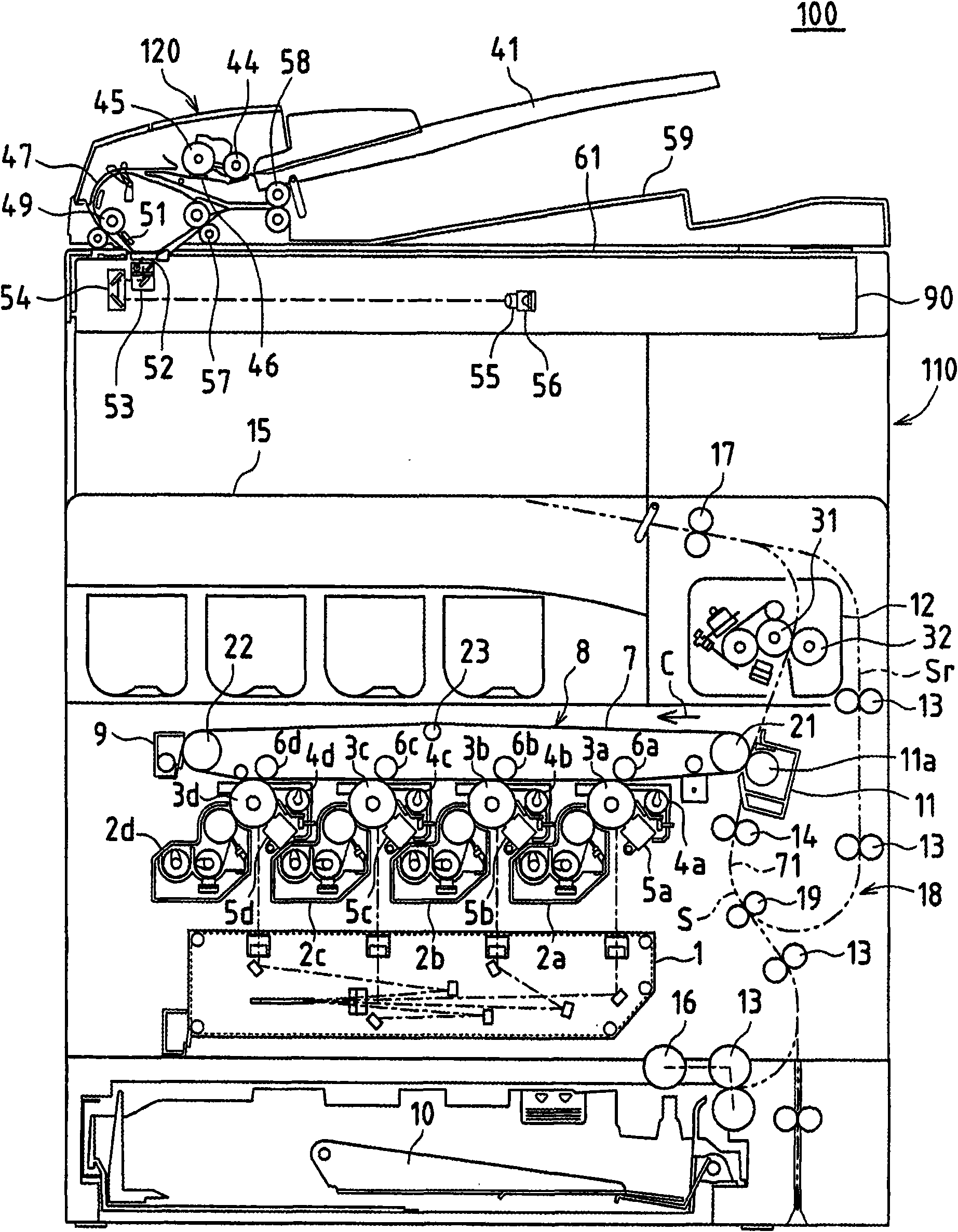
[0031] figure 1 It is a cross-sectional view showing an image forming apparatus 100 to which an embodiment of the fixing device of the present invention is applied. This image forming apparatus 100 includes: a document reading device 120 for reading a document image, and a system for forming the image of the document read by the document reading device 120 or an image received from the outside in color or monochrome on recording paper. Device body 110 .

[0032] In the original document reading device 120, when the original document is placed on the original document placement tray 41, the pickup roller 44 is pressed against the surface of the original document and rotates, the original document is pulled out from the original document placement tray 41, and the original document passes through the gap between the separation roller 45 and the separation pad 4...


PUM


Abstract

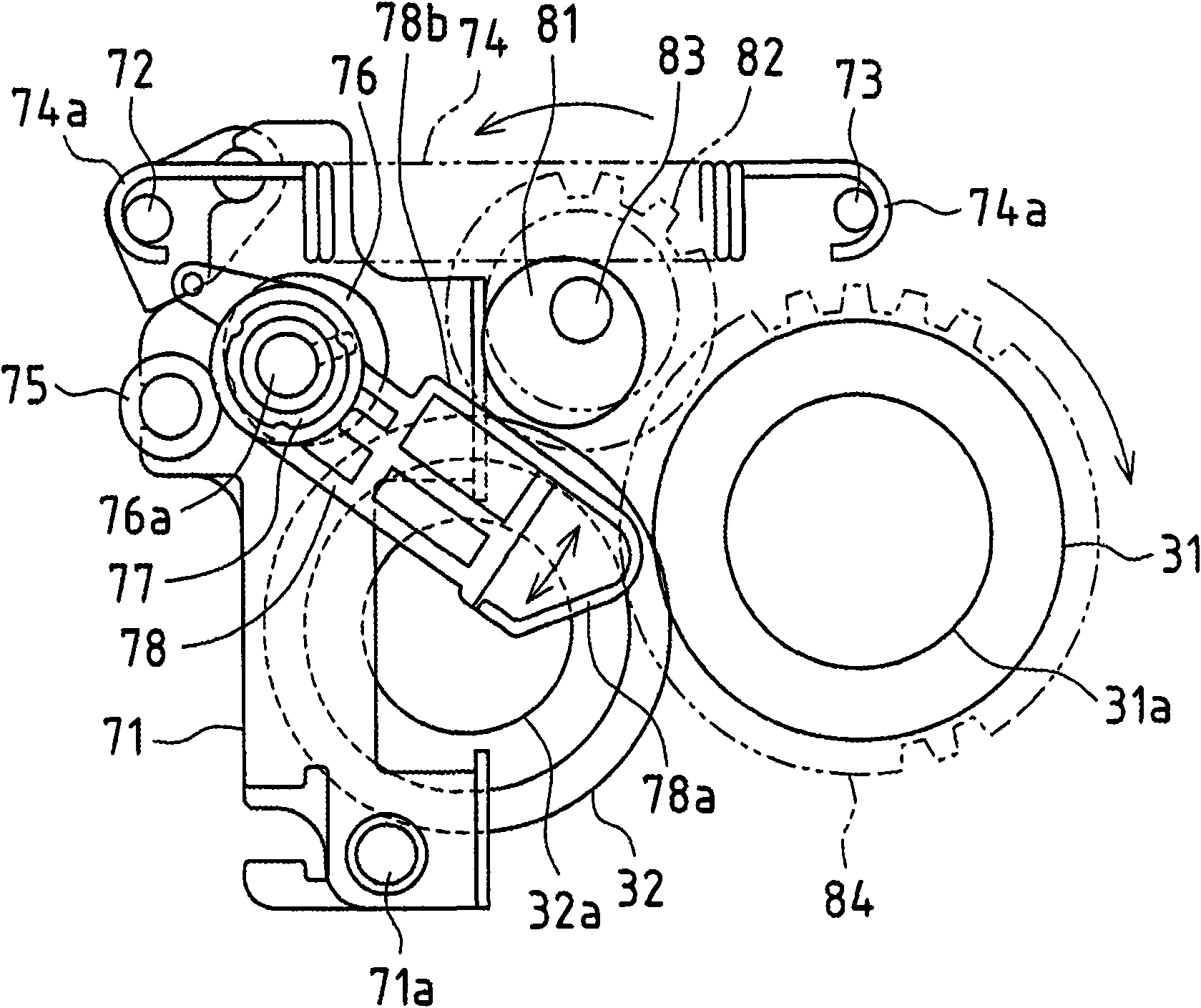
In one embodiment, when a hot roller is driven to rotate, a driving gear rotates so that a swing gear and a swing cam rotate. Then, a sliding contact edge on the right side of a swing lever that abuts against the circumferential face of the swing cam repeatedly moves up and down, and the swing lever repeatedly rotates clockwise and counterclockwise with a shaft of a pressure release cam as the center. At this time, since only the clockwise rotation of the swing lever is transmitted via a one-way clutch to the shaft of the pressure release cam, the clockwise rotation is intermittently transmitted to the shaft of the pressure release cam. As a result of this, the pressure release cam intermittently rotates clockwise, and the pressure release cam pushes away a roller of a displacement frame, so that the pressure roller separates from the hot roller.

Description

[0001] This application claims priority based on Japanese Patent Application No. 2008-165968 filed in Japan on June 25, 2008. And quote its entire content in this application. technical field [0002] The present invention relates to a fixing device applied to electrophotographic image forming devices such as copiers, facsimile devices, and printers. Background technique [0003] In such an electrophotographic image forming apparatus, an electrostatic latent image is formed on the surface of the photoreceptor drum, and the electrostatic latent image on the surface of the photoreceptor drum is developed with toner to form a toner image on the surface of the photoreceptor drum. The toner image is transferred from the photoreceptor drum to the recording paper, and the recording paper is heated and pressurized to fix the toner image on the recording paper. [0004] Fixing of the toner image on the recording paper is performed by a fixing device. In the fixing device, the recor...

Claims


Application Information

Patent Timeline
Patent Type & Authority Applications(China)
IPC IPC(8): G03G15/20G03G15/01
CPCG03G15/2067G03G15/2032
Inventor 塚本公秀中村博一山中孝师浪崎广介
Owner SHARP KK
Learn More