Three-position locking device for withdrawable circuit breaker

A drawer-type circuit breaker and locking device technology, applied in switchgear, pull-out switchgear, switchgear components and other directions, can solve problems such as complex structure, and achieve the effects of convenient assembly, simple structure and reliable operation

Inactive Publication Date: 2011-06-29
ZHEJIANG TENGEN ELECTRIC
View PDF2 Cites 0 Cited by
  • Summary
  • Abstract
  • Description
  • Claims
  • Application Information

AI Technical Summary

Problems solved by technology

[0002] In the withdrawable circuit breaker, there are usually three states of separation, test and connection. In order to make the circuit breaker in the above three positions, it can be accurately positioned to avoid misoperation, and a drawer circuit breaker with a locking device appears. When the circuit breaker is in any position of separation, test and connection, the locking device can be used to lock it, and the circuit breaker can only be moved after unlocking, as in the patent documents of Chinese Patent No. 02264483.0 and 200620125962.0 A locking device with such a function is disclosed, and since the two patent documents use the locking piece with the square shaft to achieve the locking function, it is obvious that the structure of this method is very complicated

Method used


Image

  • Three-position locking device for withdrawable circuit breaker
  • Three-position locking device for withdrawable circuit breaker
  • Three-position locking device for withdrawable circuit breaker

Examples


Embodiment Construction

[0017] Embodiments of the present invention are now further described in conjunction with the accompanying drawings:

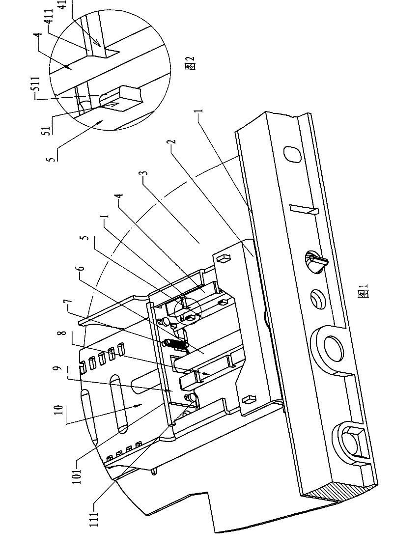
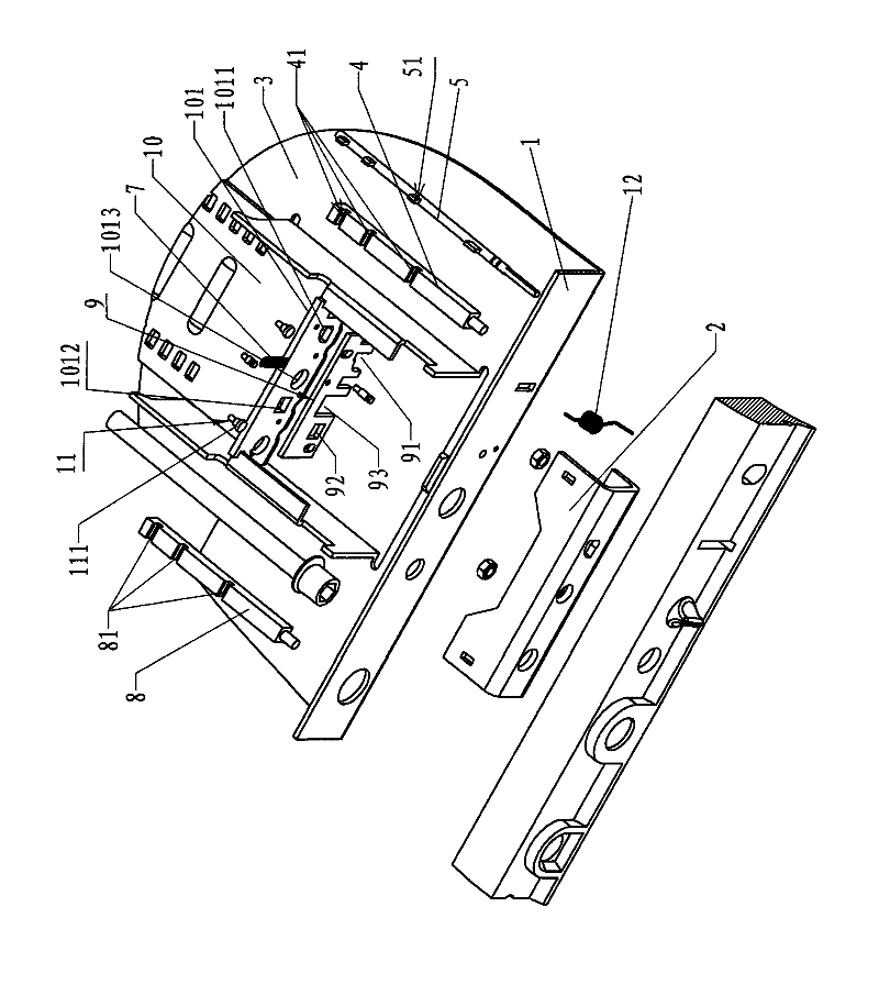
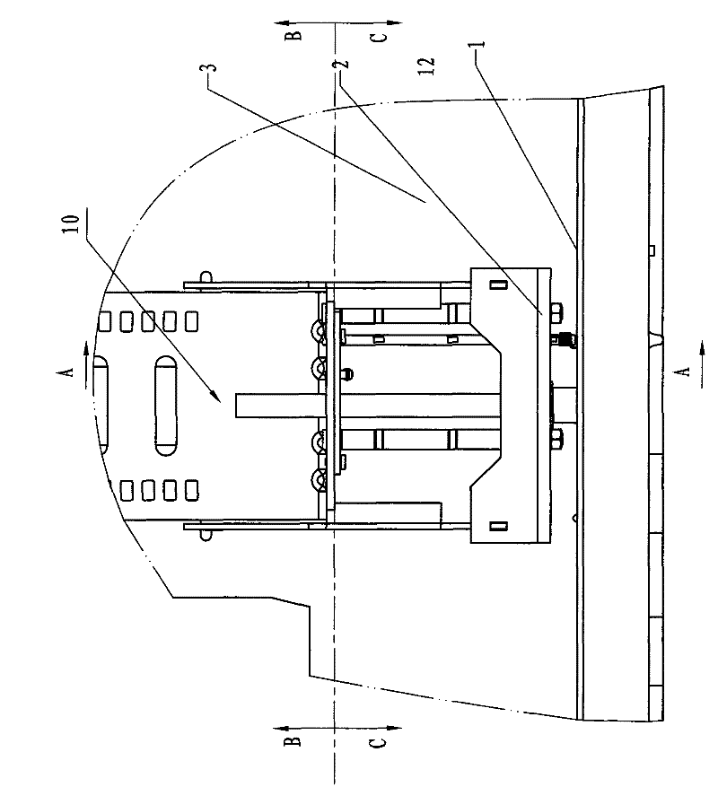
[0018] As shown in the figure, an embodiment of a three-position locking device of a drawer type circuit breaker in the present invention includes two supports 1 and 2 arranged on the bottom plate 3, and two supports 1 and 2 arranged on the bottom plate 3 and located in front of the supports 1 and 2. Skateboard 10, the transmission screw rod 6 that is installed on the front support 2 and connected with the slide plate 10, is fixedly provided with the first square shaft 8 on the front support 2, and the front end of this first square shaft 8 passes through the front end of the slide plate 10. The vertical plate 101 is provided with three grooves 81 on the first square shaft 8, and the rear side of the vertical plate 101 is attached with a clamping plate 9 parallel to the vertical plate 101, and a clamping plate 9 is also provided on the rear side of the clamping...


PUM


Abstract

The invention relates to a three-position locking device for a withdrawable circuit breaker, comprising two support seats which are arranged on a base plate, a sliding plate which is arranged on the base plate and is positioned in front of the support seats, and a transmission screw rod which penetrates through the support seats and is connected with the sliding plate, wherein, a part of the transmission screw rod, which is adjacent to a base part, is provided with a plurality of circumferentially distributed clamp grooves, a square shaft is additionally arranged between the two support seats, the right lateral face of the square shaft is provided with three grooves, the opening of each groove is provided with a chamfered bevel edge, and an unlocking button is arranged on a rear support seat and drives a clamp plate to shift by the unlocking shaft; and the unlocking shaft is a square shaft, a square hole is arranged on the card plate, the unlocking shaft penetrates through the square hole and extends into the front support seat, a compression spring is arranged on the front end of the unlocking shaft on the front support seat so as to enable the unlocking shaft to shift backwards,the right side edge of the unlocking shaft is provided with a dummy club of which the front lateral face is an inclined plane, a square notch is arranged on the dummy club, the height of the notch isnot larger than the height of the chamfered bevel edge of each groove, and the width of the square hole of the card plate is no less than the width of the dummy club of the unlocking shaft. The invention has the advantages of simple structure and reliable running.

Description

technical field [0001] The invention relates to a circuit breaker, in particular to a three-position locking device for a drawer type circuit breaker. Background technique [0002] In the withdrawable circuit breaker, there are usually three states of separation, test and connection. In order to make the circuit breaker in the above three positions, it can be accurately positioned to avoid misoperation, and a drawer circuit breaker with a locking device appears. When the circuit breaker is in any position of separation, test and connection, the locking device can be used to lock it, and the circuit breaker can only be moved after unlocking, as in the patent documents of Chinese Patent No. 02264483.0 and 200620125962.0 A locking device with such a function is disclosed, and since both of these two patent documents use a locking piece with a square shaft to achieve the locking function, it is obvious that the structure of this method is very complicated. Contents of the inve...

Claims


Application Information

Patent Timeline
Patent Type & Authority Patents(China)
IPC IPC(8): H02B11/02H02B11/173
Inventor 袁波李思振令狐绍江李芃
Owner ZHEJIANG TENGEN ELECTRIC
Why Eureka
Try Eureka