Motor

A technology for a motor and a rotating shaft is applied in the field of motors that can prevent bearings and rotors from loosening with the help of a stator group. Convenience and rotational stability, improved rotational stability, and the effect of preventing rotor loosening

Active Publication Date: 2012-07-04
SUNONWEALTH ELECTRIC MACHINE IND
View PDF5 Cites 0 Cited by
  • Summary
  • Abstract
  • Description
  • Claims
  • Application Information

AI Technical Summary

Problems solved by technology

[0004] Furthermore, since the existing motor must be combined with the locking groove 811 of the rotating shaft 81 by means of the retaining ring 73 in order to prevent the rotor 80 from getting loose, after the existing motor is assembled, the rotor 80 The rotating shaft 81, the bearing 72, the buckle 73 and other related components must complete the coupling relationship in the shaft tube 71, so it is difficult to further confirm whether the components in the shaft tube 71 are indeed combined with each other, resulting in difficulty in grasping the existing The assembly quality of the motor, and it will also cause poor assembly convenience

Method used


Image

  • Motor
  • Motor
  • Motor

Examples


Embodiment Construction

[0032] In order to make the above-mentioned and other objects, features and advantages of the present invention more comprehensible, the preferred embodiments of the present invention are specifically cited below, together with the accompanying drawings, as follows:

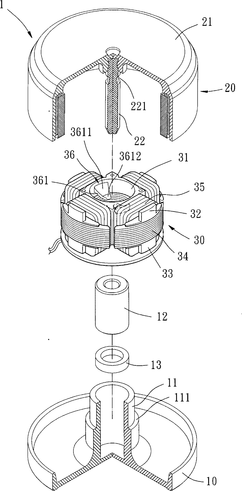
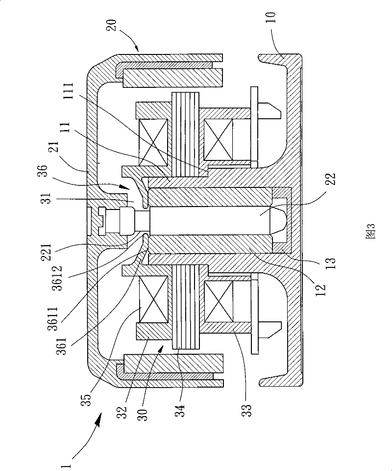
[0033] Please refer to figure 2 and 3 As shown, the motor 1 of the first embodiment of the present invention mainly includes a casing 10 , a rotor 20 and a stator assembly 30 . in:

[0034] A shaft tube 11 is arranged in the center of the shell base 10, and the bottom of the shaft tube 11 is closed, and a bearing 12 and a wear-resistant plate 13 and other components can be placed in the shaft tube 11. In addition, the shaft tube 11 A positioning portion 111 is formed on the outer peripheral wall in the radial direction.

[0035] The rotor 20 includes a hub 21 and a rotating shaft 22. Several blades (not shown) can be formed on the outer peripheral surface of the hub 21, so that the rotor 20 can be used as a ...


PUM


Abstract

The invention relates to a motor which comprises a shell seat, a rotor and a stator set, wherein a shaft tube is arranged in the center of the shell seat, and a bearing is put into the shaft tube; the rotor is provided with a rotation axis which can be combined with the bearing, and a ring groove is arranged in the outer peripheral face of the rotation axis; and the stator set provided with an assembly hole for being sleeved in the outer peripheral wall of the shaft tube is formed by cladding silicon-steel sheets by an upper insulating sleeve and a lower insulating sleeve and winding a metal coil, wherein a limit part arranged in the inner peripheral face of the upper insulating sleeve can limit the bearing and prevent the rotor from loosing so as to effectively enhance the assembly convenience and the rotary stability of the motor.

Description

technical field [0001] The invention relates to a motor, in particular to a motor which can simultaneously prevent bearings and rotors from loosening by means of a stator assembly. Background technique [0002] Please refer to figure 1 As shown, the conventional motor includes a casing 70 , a rotor 80 and a stator assembly 90 . The shell base 70 has a hollow shaft tube 71 in the center, and a bearing 72, a retaining ring 73, an oil seal cover 74 and other components can be placed inside the shaft tube 71; the rotor 80 has a rotating shaft 81 in the center, and the rotating shaft 81 is rotatably combined with the bearing 72, and the outer peripheral surface of the rotating shaft 81 forms a locking groove 811, and the locking groove 811 is adjacent to the bottom of the rotating shaft 81 for engaging and combining the snap ring 73; the stator The group 90 is mounted on the outer peripheral surface of the shaft tube 71 so as to drive the rotor 80 to rotate. [0003] Generally...

Claims


Application Information

Patent Timeline
Patent Type & Authority Patents(China)
IPC IPC(8): H02K7/08H02K1/12H02K5/167
Inventor 洪银树王启民
Owner SUNONWEALTH ELECTRIC MACHINE IND
Why Eureka
Try Eureka