Electromagnetic relay

An electromagnetic relay, electromagnetic technology, applied in electromagnetic relays, relays, detailed information of electromagnetic relays, etc., can solve the problems of the number of parts, many assembly processes, complex structure, etc., and achieve the effect of fewer assembly processes, simple structure, and low magnetic resistance.

Active Publication Date: 2010-01-06
ORMON CORP
View PDF1 Cites 31 Cited by
  • Summary
  • Abstract
  • Description
  • Claims
  • Application Information

AI Technical Summary

Problems solved by technology

[0006] However, in the above-mentioned electromagnetic relay, one upper magnetic piece 13 is used to apply force to the movable contact 15 by the pressing spring 16, and on the other hand, the other lower magnetic piece 20 is pressed to the movable contact 15 by the pressing spring 23. Force is applied, so there are problems with the number of parts, many assembly processes, and complex structure

Method used


Image

  • Electromagnetic relay
  • Electromagnetic relay
  • Electromagnetic relay

Examples


Embodiment Construction

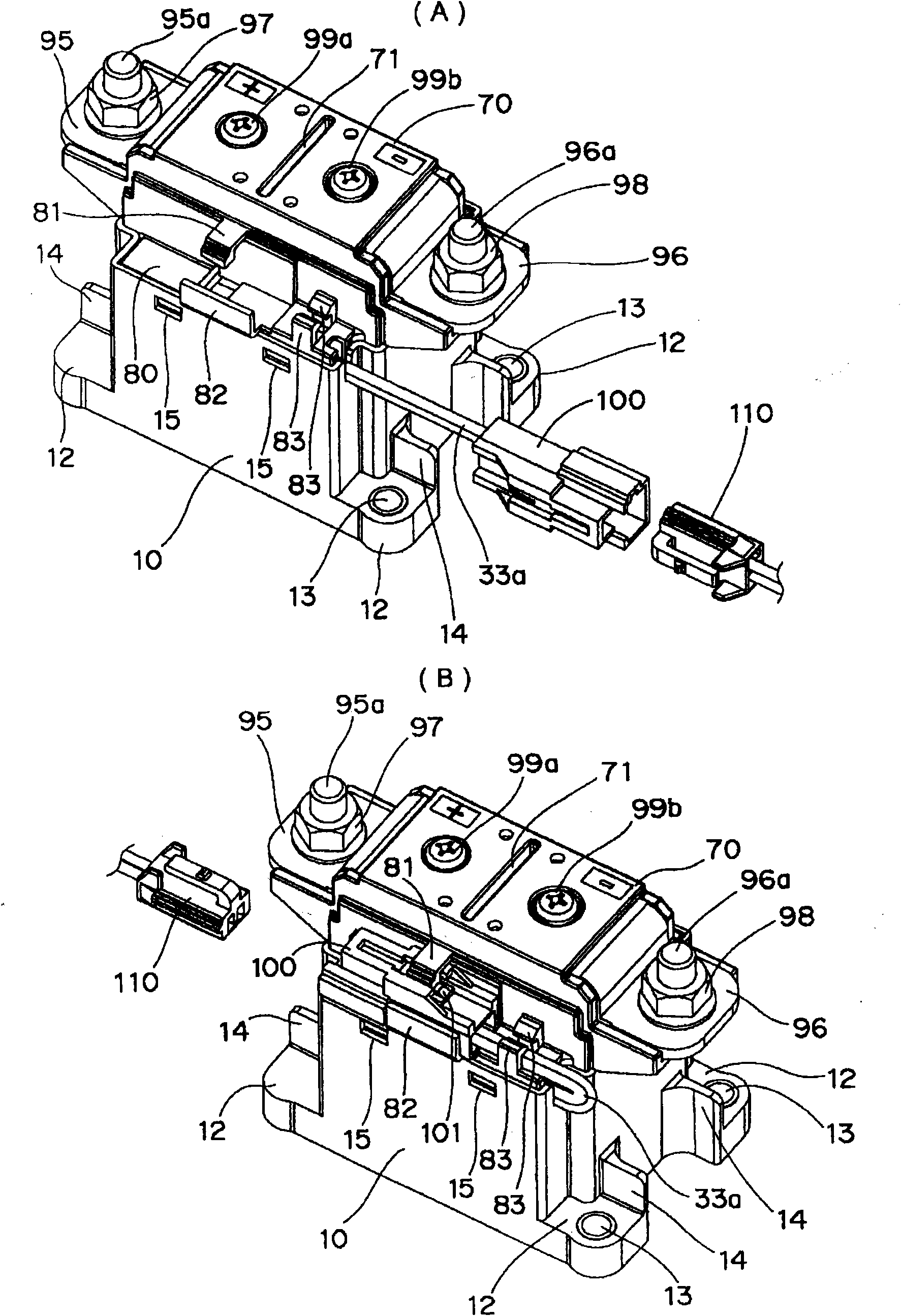
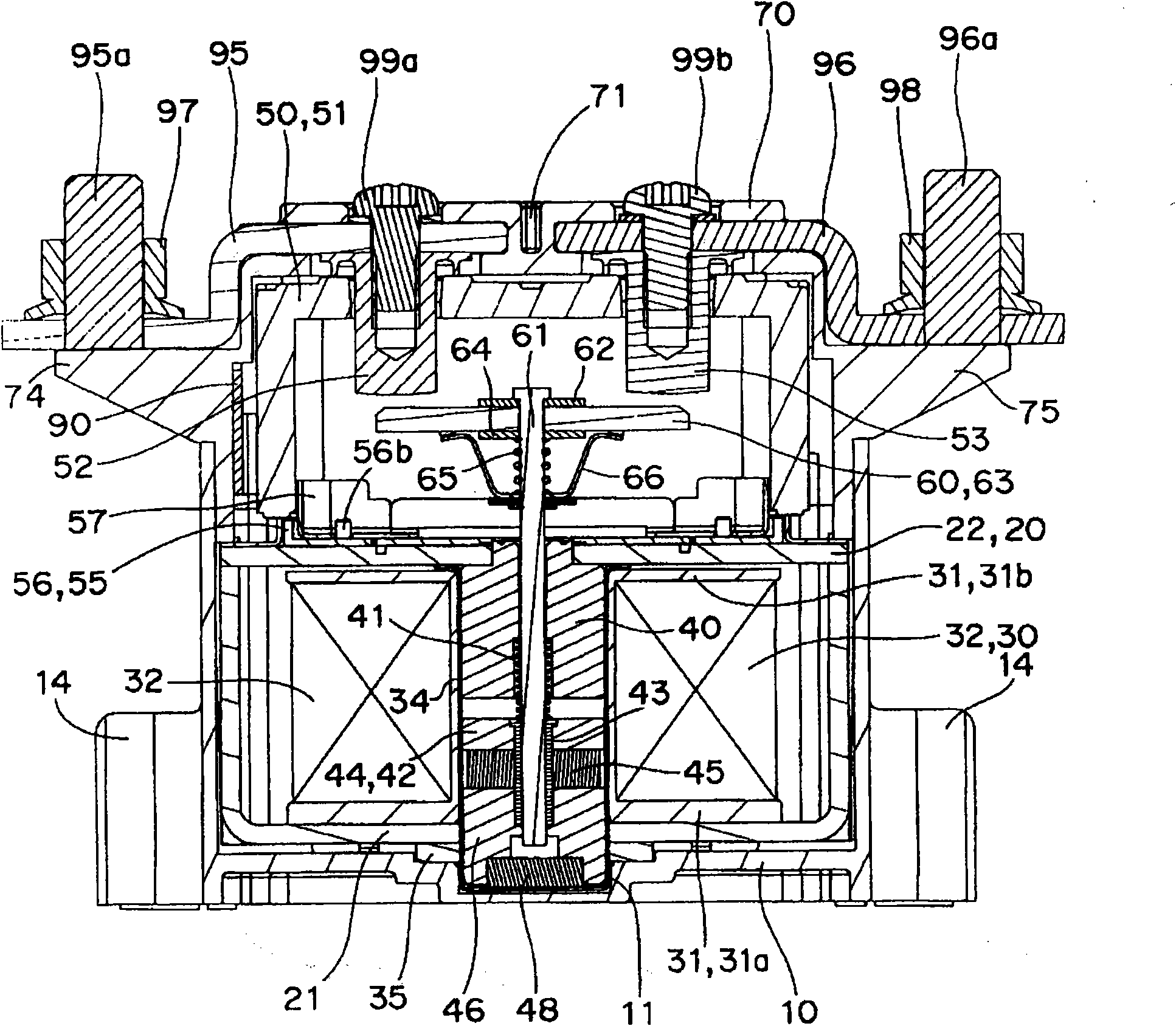
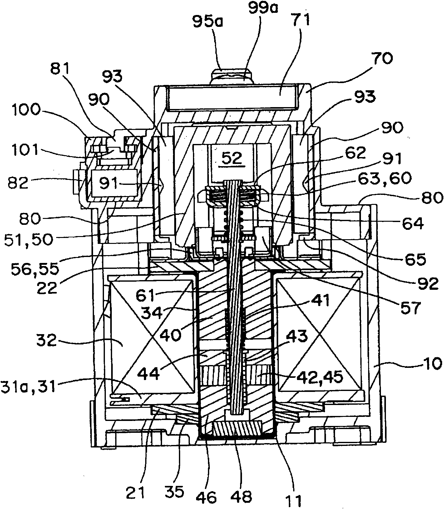
[0083] refer to Figure 1 to Figure 14 An electromagnetic relay for power loads, which is an embodiment of a contact device to which the present invention is applied, will be described.

[0084] like Figure 1 to Figure 13 As shown, the electromagnetic relay for power loads of the first embodiment has a general configuration: a drive mechanism assembly 20 and a contact mechanism assembly 50 integrated up and down are accommodated in a case (base) 10, and a cover 70 is fitted covered on the casing 10.

[0085] like Figure 4 As shown, the housing 10 is box-shaped with a bottom surface capable of accommodating the drive mechanism assembly 20 described later, and a fitting recess 11 for positioning the drive mechanism assembly 20 ( figure 2 and image 3 ). In addition, the casing 10 is provided with mounting holes 13 and reinforcing ribs 14 protruding from a base portion 12 protruding laterally from the lower edge portion of the outer peripheral corner portion. However, one...


PUM


Abstract

This invention provides an electromagnetic relay capable of preventing drawbacks by electromagnetic repulsion, and having a small number of components and reducing the number of assembly steps, and having a simple structure. An electromagnetic relay for contacting and separating both ends of a movable contact arranged at one end of a drive shaft, which reciprocates in an axis center direction based on excitation and demagnetization of an electromagnet block, to a pair of adjacently arranged fixed contacts is provided. When the movable contact contacts to a pair of fixed contacts, a second electromagnetic iron piece forming a magnetic circuit with a first electromagnetic iron piece pushes the movable contact to the pair of fixed contacts.

Description

technical field [0001] The invention relates to an electromagnetic relay, in particular to an electromagnetic switch for power load. Background technique [0002] Conventionally, in an electromagnetic switch for power loads, when an abnormal current flows when the contacts are opened and closed, an electromagnetic repulsive force acts between the fixed contact and the movable contact. Therefore, the contact pressure decreases, the contact resistance increases, and Joule heat increases rapidly, or the contacts separate to generate arc heat, thereby welding the movable contact and the fixed contact. [0003] In order to prevent such contact welding, for example, a movable contact supporting device of a switch is disclosed, that is, a movable contact is arranged in a window hole provided on the supporting table, and a movable contact is arranged in a sliding restriction hole. The lower magnetic sheet is arranged, the upper magnetic sheet is mounted on the upper surface of the ...

Claims


Application Information

Patent Timeline
Patent Type & Authority Applications(China)
IPC IPC(8): H01H51/00H01H50/20
CPCH01H1/2008H01H51/2227H01H1/54H01H9/443H01H50/546H01H2050/025H01H50/38
Inventor 田中弘泰吉原育广桥本竜一广木和亲辻秀明
Owner ORMON CORP
Why Eureka
Try Eureka