
Stamping method for numerical control stamping machine tool

A punching machine tool and punching die technology, applied in the field of machinery, can solve problems such as size tolerance, part deformation, uncontrollable dimensional accuracy, etc., to achieve the effects of improving stability, avoiding easy deformation, and improving work efficiency

Inactive Publication Date: 2010-01-13
上海运通工程机械有限公司
View PDF0 Cites 9 Cited by
  • Summary
  • Abstract
  • Description
  • Claims
  • Application Information

AI Technical Summary

Problems solved by technology

With the development of precision in the manufacturing industry, the dimensional accuracy requirements for the position of the part holes and the roundness of the parts are increasing. If traditional stamping machine tools and stamping methods are used to manufacture such parts, it is easy to cause deformation of the parts and out-of-tolerance dimensions.
It is impossible to control the dimensional accuracy within the acceptable range during the stamping process, resulting in parts that cannot meet the drawing requirements

Method used


Image

  • Stamping method for numerical control stamping machine tool
  • Stamping method for numerical control stamping machine tool
  • Stamping method for numerical control stamping machine tool

Examples


Embodiment Construction

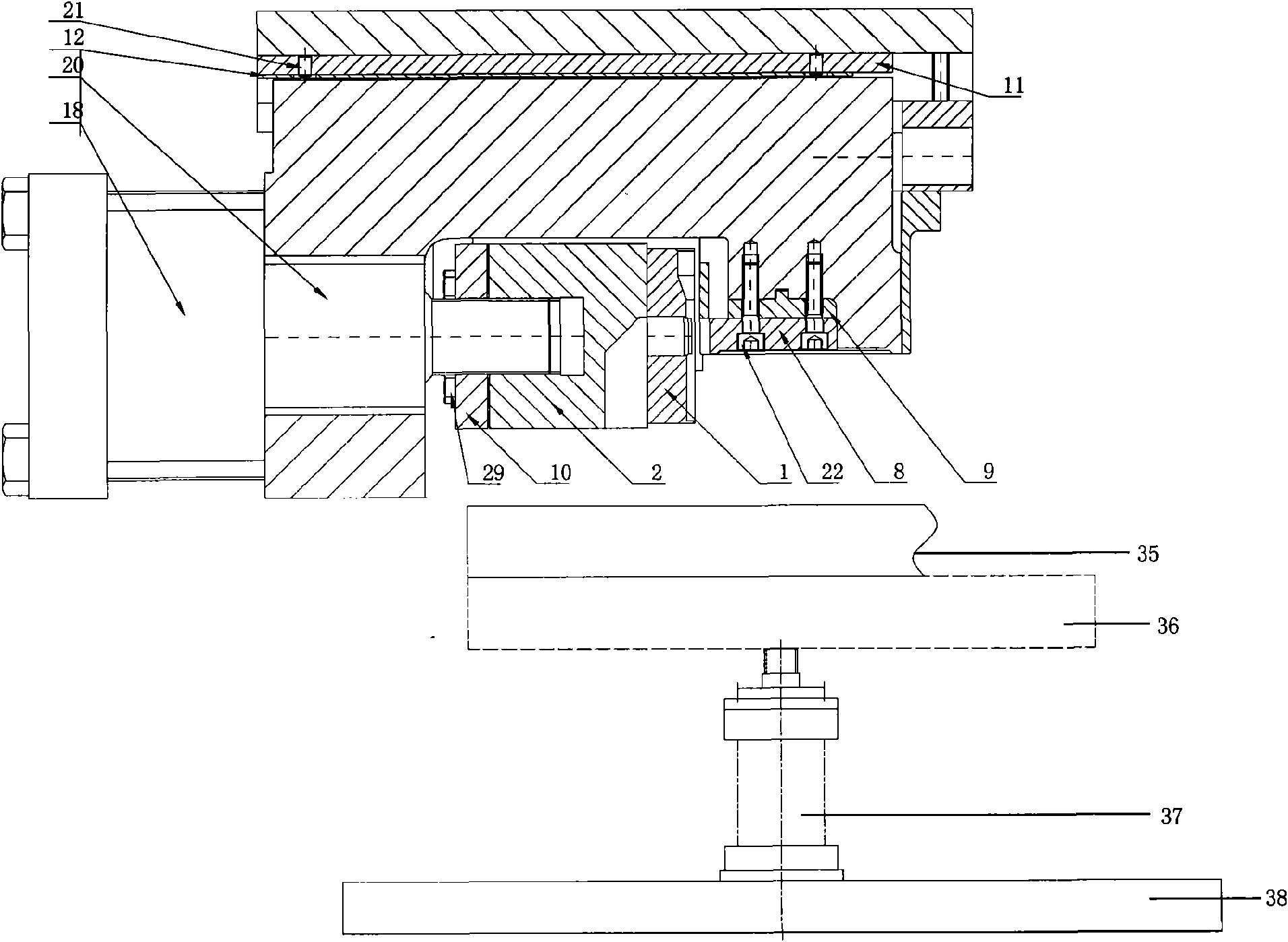
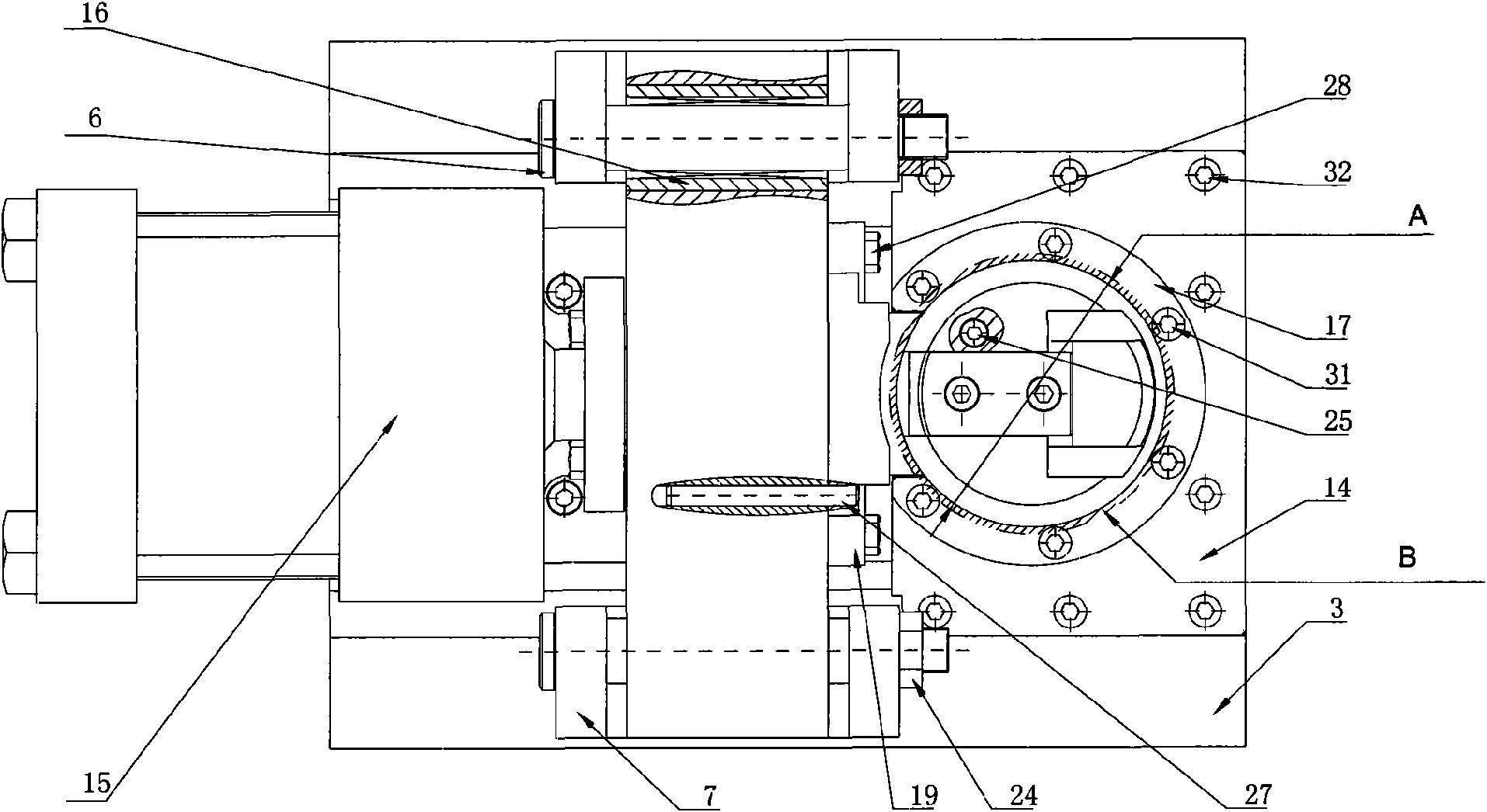
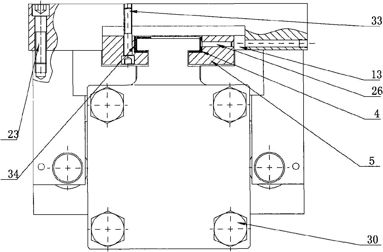
[0017] see figure 1 and combine figure 2 and image 3 , the die device shown in the figure includes a male die member and a female die member. The male mold member includes a lower mold 1 , a lower mold sliding seat 2 , a lower molding plate 19 , a cylindrical guide rail 6 , a cylindrical guide rail seat 7 , an inner corner thin nut 24 , a compression nut 10 , and a hexagon head bolt 28 . see figure 2 There are two cylindrical guide rail seats 7, which are respectively installed on both sides of the cylindrical guide rail 6. One side is fixed by the cylindrical head of the cylindrical guide rail 6, and the other side is fixed by the inner corner thin nut 24. A steel sleeve 16 is installed between the lower die sliding seat 2 and the cylindrical guide rail 6 . The two cylindrical guide rail seats 7 define the movement path of the lower die sliding seat 2 . The hexagon head bolts 28 fix the lower die 1 on the lower die sliding seat 2 through the compression nut 10, so tha...


PUM


Abstract

The invention discloses a stamping method for a numerical control stamping machine tool, and relates to stamping technology. In the stamping method provided by the invention, a die stamping device on the used numerical control stamping machine tool is provided with a fixed piece which is arranged telescopically. When a workpiece is stamped, the fixed piece is fixed to the side of the current stamping position of the workpiece; and after the current station stamping is finished, the fixed piece retracts to the primary position. The dimension stability of the workpiece can be ensured by adopting the stamping method of the invention. The stamping method for the numerical control stamping machine tool can continuously form waist holes with different heights on the workpiece so as to improve the working efficiency.

Description

technical field [0001] The invention relates to stamping technology in the mechanical field, in particular to a stamping method of a numerically controlled stamping machine tool for punching waist holes on workpieces. Background technique [0002] At present, ordinary stamping is a processing method that uses stamping equipment and dies to permanently deform or separate sheets or blanks of various specifications under pressure to make parts of various shapes. However, there are certain limitations. For example, in the punching process of cylindrical parts, the punching density of the parts is relatively large, which requires multiple punching to complete. With the development of manufacturing precision direction, the position of parts holes and the dimensional accuracy requirements of parts roundness increase. If traditional stamping machine tools and stamping methods are used to manufacture such parts, it is easy to cause deformation of parts and out of tolerance. The dime...

Claims


Application Information

Patent Timeline
IPC IPC(8): B21D28/24B21D28/34B21D43/00
Inventor 王一平张霞光翁伟雄王琼龚琦
Owner 上海运通工程机械有限公司
Learn More