High-pressure reducing valve

A pressure reducing valve, high pressure technology, applied in the field of high pressure pressure reducing valve, can solve the problems affecting the stability of the outlet pressure, the change of the outlet pressure, and the change of the throttle area of ​​the orifice, so as to improve the accuracy of the pressure stabilization, reduce the area of ​​the piston, The effect of reducing friction

Active Publication Date: 2010-01-13
CAMA LUOYANG GAS SUPPLY
1 Cites 38 Cited by

AI-Extracted Technical Summary

Problems solved by technology

[0003] 1. When the inlet pressure fluctuates greatly, the inlet pressure fluctuation is transmitted to the piston through the force acting on the spool, so that the piston drives the spool to move together, changing the throttle area of ​​the orifice and changing the outlet pressure. Affect the stability of outlet pressure
[0004] 2. When the outlet pressure requirement of the pressure reducing valve is high, the design of the piston and the pressure regulating spring is difficult, and the rigidity of the pressure regulating spring is very hard, which makes the outlet pressure fluctuate greatly and the precision of the pressure regulation is low; When adjusting the pressure knob, it not only takes time and effort to adjust, but also makes the entire pressure reducing valve bulky and heavy, whi...

Method used

As shown in Fig. 1 and Fig. 2, what arrow shows in the figure is gas flow direction, and high-pressure relief valve provided by the invention comprises upper and lower valve body 7,14 by threaded connection, passes through in upper valve body 7 A piston 9 is inserted into the sliding seal of the piston installation hole, and a spring pressure regulating device is provided on the top of the piston 9. The spring pressure regulating device includes a pressure regulating knob 1 screwed on the top of the upper valve body 7, and a pressure regulating shaft firmly connected with the pressure regulating knob 1. 3. Rotate the pressure-regulating spring seat 5 assembled on the lower end of the pressure-regulating shaft 3, the piston seat 8 assembled on the top of the piston 9, and the pressure-regulating spring 6 mounted between the pressure-regulating spring seat 5 and the piston seat 8. A thrust ball bearing 4 is installed between the pressure regulating shaft 3 and the pressure regulating spring seat 5, and the pressure regulating spring 6 is connected between the pressure regulating spring seat 5 and the piston seat 8; the lower end of the piston 9 is embedded with a non-metallic overflow Seat 22, the axis of piston 9 is provided with an overflow flow hole, and the outer diameter of piston 9 is processed with multiple ring grooves and O-ring sealing devices. The compression amount of the ring is small, which is beneficial to reduce the friction force when the piston 9 moves. The outer diameter of the piston 9 matches the piston installation hole on the upper valve body 7, and the spherical surface on the upper part of the piston 9 matches the tapered hole on the piston seat 8. Surface line contact, this structural design can make the diameter of the piston 9 smaller, light in weight, small in inertia, small in friction, and flexible in movement. At the same time, due to the reduction of the piston area, the design of the pressure regulating spring 6 is easy, and the spring stiffness is small, which is beneficial to improve the outlet pressure regulation accuracy of the pressure reducing valve, improve the sensitivity and improve the response speed, and at the same time, due to the size of the pressure regulating spring 6 The small structure makes the entire pressure reducing valve small in size, light in weight and compact in structure. The piston seat 8 is pressed on the seat surface of the upper valve body 7 under the action of the pressure regulating spring 6. The upper end of the pressure regulating spring 6 is a pressure regulating spring seat 5, and a thrust is installed between the pressure regulating spring seat 5 and the pressure regulating shaft 3. The ball bearing 3 and the thrust ball bearing 3 make pressure regulation flexible, saving time and effort. The pressure regulating knob 1 and the pressure regulating shaft 3 are fixedly connected together, and the pressure regulating shaft 3 and the upper valve seat 2 adjust the compression amount of the pressure regulating spring 6 through screw transmission.
The lower valve body 14 is provided with an air inlet, an air outlet and an air inlet chamber and an air outlet chamber communicated with the air inlet and outlet respectively, and the bottom end of the piston 9 is located in the air outlet chamber above, and the lower valve body In 14, a valve seat 12...

Abstract

The invention relates to a high-pressure reducing valve. A throttling hole which is communicated with an air inlet cavity and an air outlet cavity and a valve core which axially and movably penetrates through the throttling hole are arranged in a valve seat; the valve core is provided with a throttling conical surface which is in movable and sealing fit with a lower hole opening of the throttling hole in the air inlet cavity; the upper end of the valve core supports against a piston in a matching mode; the lower end of the valve core is elastically assembled in the valve body through an offsetting spring; the throttling conical surface of the valve core is axially arranged at the middle part of the air inlet cavity just opposite to the an air inlet; the lower end of the valve core is provided with a lower valve post which is assembled in the valve seat in a sliding and sealing mode; and the diameter of the lower valve post is equal to the aperture of the throttling hole of the valve seat. In the invention, the diameter of the lower valve post is equal to the aperture of the throttling hole of the valve seat so that an axial action force of inlet pressure acting on the valve core is zero so as to eliminate the influence of the fluctuation of inlet pressure on outlet pressure and improve the pressure stabilizing precision.

Application Domain

Valve members for absorbing fluid energyEqualizing valves +2

Technology Topic

PistonHigh pressure +3

Image

  • High-pressure reducing valve
  • High-pressure reducing valve

Examples

  • Experimental program(1)

Example Embodiment

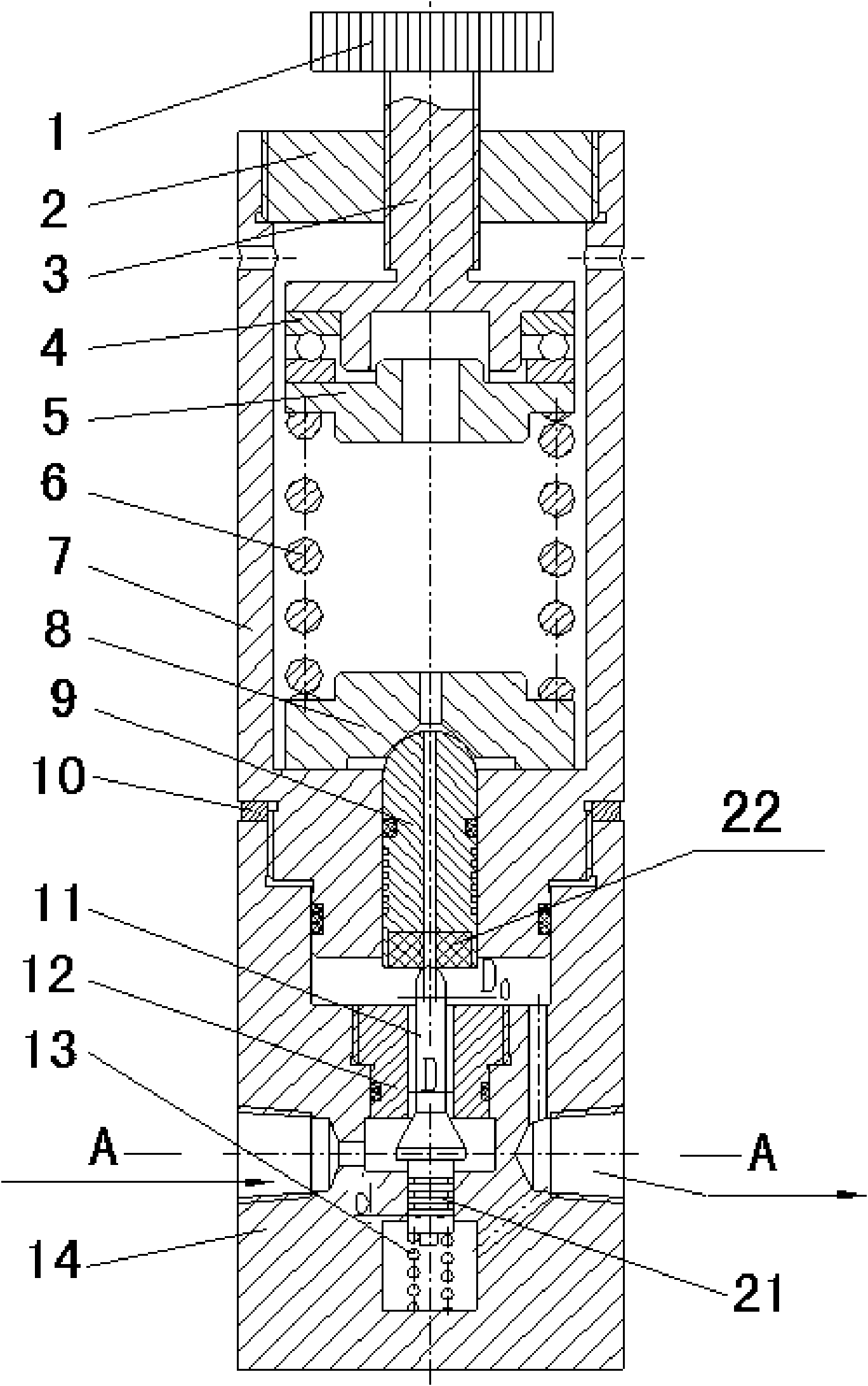
[0028] Such as figure 1 , figure 2 As shown, the arrow in the figure shows the gas flow direction. The high-pressure pressure reducing valve provided by the present invention includes upper and lower valve bodies 7, 14 connected by threads. The upper valve body 7 slides and seals the piston through the piston mounting hole. 9. The top of the piston 9 is provided with a spring pressure regulating device. The spring pressure regulating device includes a pressure regulating knob 1 screwed on the top of the upper valve body 7, a pressure regulating shaft 3 fixedly connected to the pressure regulating knob 1, and a rotating assembly at the lower end of the pressure regulating shaft 3. The pressure regulating spring seat 5, the piston seat 8 assembled at the top of the piston 9, and the pressure regulating spring 6 mounted between the pressure regulating spring seat 5 and the piston seat 8. A thrust ball bearing 4 is installed between the pressure regulating shaft 3 and the pressure regulating spring seat 5, and the pressure regulating spring 6 is connected between the pressure regulating spring seat 5 and the piston seat 8; the lower end of the piston 9 is embedded with inherent non-metallic overflow Seat 22, the axis of the piston 9 is provided with an overflow flow hole, and the outer diameter of the piston 9 is machined with multiple ring grooves and O-ring sealing devices. The ring grooves enable the piston 9 to have a good centering performance. The compression of the ring is small, which is beneficial to reduce the friction when the piston 9 moves. The outer diameter of the piston 9 matches the piston mounting hole on the upper valve body 7, and the upper spherical surface of the piston 9 matches the tapered hole on the piston seat 8. Face-to-line contact, this structural design can make the piston 9 have a small diameter, light weight, small inertia, low friction, and flexible movement. At the same time, due to the reduction of the piston area, the design of the pressure regulating spring 6 is easy, and the spring stiffness is small, which is conducive to improving the outlet pressure regulation accuracy of the pressure reducing valve, increasing the sensitivity and improving the response speed. At the same time, due to the size of the pressure regulating spring 6 The small structure makes the entire pressure reducing valve small in size, light in weight and compact in structure. The piston seat 8 is pressed on the seat surface of the upper valve body 7 under the action of the pressure regulating spring 6. The upper end of the pressure regulating spring 6 is a pressure regulating spring seat 5, and a thrust is installed between the pressure regulating spring seat 5 and the pressure regulating shaft 3. Ball bearing 3 and thrust ball bearing 3 make pressure adjustment flexible, saving time and effort. The pressure regulating knob 1 and the pressure regulating shaft 3 are firmly connected together, and the pressure regulating shaft 3 and the upper valve seat 2 are driven by a thread to adjust the compression amount of the pressure regulating spring 6.
[0029] The lower valve body 14 is provided with an air inlet, an air outlet, and an air inlet cavity and an air outlet cavity respectively communicating with the inlet and outlet ports. The bottom end of the piston 9 is arranged in the upper air outlet cavity, and the lower valve body 14 is in A valve seat 12 is provided between the lower air inlet cavity and the upper air outlet cavity. The valve seat 12 is provided with a throttle hole which is connected between the air inlet cavity and the air outlet cavity. A valve core 11 is inserted and fitted in the throttle hole. , The valve core 11 includes a frustum structure matched with the lower orifice of the orifice, and an upper spool and a lower spool 21 connected to the top and bottom ends of the frustum. The throttle cone of the frustum is set in the axial direction. In the middle of the air inlet cavity of the air inlet, the throttle cone surface of the frustum and the sharp edge of the orifice under the valve seat 12 form a throttle window, and the top of the spool on the valve core 11 presses against the bottom of the piston 9 And in the outlet cavity. A lower valve cavity is provided below the spool 11 to communicate with the air outlet, and the lower spool 21 is slidably fitted into the spool mounting hole of the lower valve body 14 and inserted directly into the lower valve cavity. The shaft diameter of the lower spool 21 is equal to the aperture D of the orifice of the valve seat 12, the lower spool 21 and the spool mounting hole are a sliding fit with a small fit gap, and the shaft diameter of the lower spool 21 has multiple openings. The ring groove, the ring groove plays a role of sealing and equalizing pressure to reduce the clamping force and friction force when the lower spool 21 moves, so that the spool 11 can move flexibly, and the lower end of the lower spool 21 is reset by the assembly in the lower valve cavity The spring 13 exerts an upward axial force. Since the upper and lower parts of the valve core 11 are in communication with the outlet cavity, this structure makes the axial force of the inlet pressure acting on the valve core 11 zero. The outlet pressure acts on the upper and lower axial forces of the valve core 11 in an upward direction. The effective area of ​​the outlet pressure acting on the valve core 11 is the contact aperture between the upper spherical surface of the valve core 11 and the non-metallic overflow seat 22 embedded in the piston 9 D 0 The sealing area formed due to the overflow aperture D 0 Very small, the upward axial force exerted by the outlet pressure on the valve core 11 is not large. Because the valve core 11 and the lower valve body 14 are in a clearance and sliding fit, the frictional force relative to the return spring 13 is very small and can be ignored. The valve core 11 is subjected to the upward axial force of both the return spring 13 and the outlet air pressure, so that the upper spherical surface of the valve core 11 is pressed and fixed on the hole in the non-metal overflow seat 22 on the piston 9.
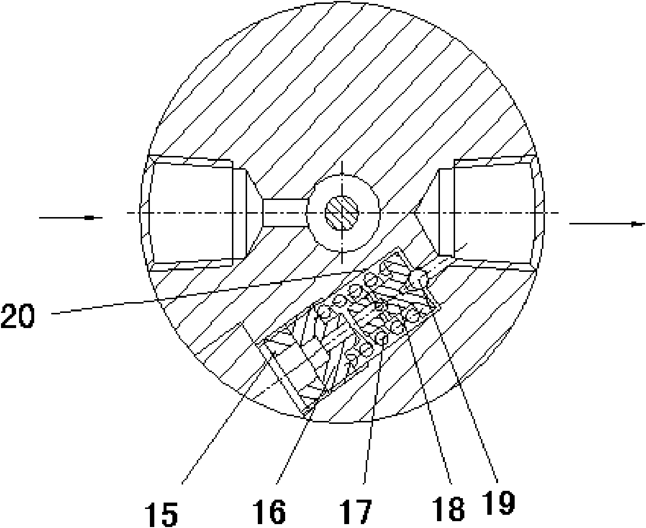
[0030] As shown in 2, the lower valve body 14 is also provided with a safety overflow channel 20 between the air outlet and the outside atmosphere, and a safety overflow device is provided in the safety overflow channel. The safety overflow device includes a pressure regulating nut 16 screwed into the safety overflow channel, a ball seat 18 top-mounted on the pressure regulating nut 16 by a safety spring 17, and a corresponding seal on the ball seat 18 and the safety overflow channel. The steel ball 19 at the orifice, the ball seat 18 and the steel ball 19 are arranged on the side of the pressure regulating nut 16 close to the air outlet of the valve body. A lock nut 15 mounted on the pressure regulating nut 16 is screwed into the safety overflow channel on the side of the pressure regulating nut 16 away from the air outlet of the valve body. When the safety overflow device is in use, the pressure regulating nut 16 compresses the safety spring 17, and the compressed safety spring 17 presses the steel ball 19 on the throttling round table of the lower valve body through the ball seat 18 to play a sealing role, and the taper hole communicates with the outlet , The outlet air pressure acts on the steel ball 19, when the outlet air pressure acts on the steel ball 19 when the pressure is greater than the safety pressure set by the safety spring 17, the steel ball 19 is lifted by the air pressure and separated from the cone surface, and the airflow is separated from the steel ball 19 The gap between the surface of the cone and the cone hole overflows, so that the outlet pressure is quickly reduced and restored to the set pressure value. When the pressure regulating nut 16 is adjusted to an appropriate safety pressure, the lock nut 15 is tightened to prevent loosening.
[0031] An adjustment washer 10 is provided between the contact end surfaces of the upper and lower valve bodies 7 and 14. When the valve body is working, the conical surface of the valve core 11 and the edge of the orifice on the lower end of the throttle hole of the valve seat 12 form an initial throttling window with a constant opening. The area of ​​this initial throttling window determines the maximum pressure reducing valve. Flow rate, by replacing the adjusting gasket 10 with different thickness, the initial throttle window area between the valve core 11 and the valve seat 12 can be adjusted to meet different maximum flow requirements.
[0032] When the pressure reducing valve of the embodiment of the present invention is working, the pressure regulating shaft 3 fixedly connected with the pressure regulating knob 1 is rotated, and the pressure regulating spring 6 is compressed through the thrust ball bearing 4 and the pressure regulating spring seat 5. The force of the pressure regulating spring 6 The piston seat 8 is transmitted to the seat surface of the upper valve body 7, and the compression amount of the pressure regulating spring 6 determines the outlet pressure of the pressure reducing valve. When there is no pressure input at the inlet of the pressure reducing valve, the return spring 13 pushes the valve core 11 upwards, and the force is applied to the piston 9 through the valve core 11. The upper spherical surface of the piston 9 contacts the piston seat 8, because the return spring 13 acts on The force on the piston seat 8 is less than the force of the pressure regulating spring 6 on the piston seat 8, and the piston seat 8 will not move upwards. At this time, the cone surface of the valve core 11 and the edge of the lower end surface of the valve seat 12 An initial throttling window with a constant opening is formed. The area of ​​this initial throttling window determines the maximum flow rate of the pressure reducing valve. The size of the initial throttling window can be changed by changing the thickness of the adjustment gasket 10 to meet different maximum flow rates. demand. When there is pressure input at the inlet of the pressure reducing valve, the inlet airflow flows into the outlet through the throttle window, and the pressure built up at the outlet gradually rises. When the outlet pressure approaches the pressure set by the pressure regulating spring 6, the return spring acting on the piston 9 13 When the sum of the upward force and the outlet air pressure acting on the lower end of the piston 9 is greater than the downward force of the pressure regulating spring 6 on the piston 9, the piston 9 moves upward, and the valve core 11 acts on the return spring 13 As the piston 9 moves upward under the force, the area of ​​the throttle window is reduced, and the effect of throttling and decompression is enhanced. When the outlet pressure reaches the set pressure, the forces on the piston 9 up and down are balanced, and the piston 9 and the valve core 11 stop moving. The outlet has a stable pressure output. When the outlet flow suddenly increases and the area of ​​the throttle window does not change, the outlet pressure must decrease. At this time, the outlet pressure acts on the piston 9 to decrease, and the pressure regulating spring 6 presses the piston 9 to move downward, and the piston 9 presses the valve. The core 11 moves downwards, the area of ​​the throttle window increases, and the throttling effect is weakened, so that the outlet pressure rises and returns to the set pressure. The enlarged throttle window area can also meet the demand for increasing the flow. In the same way, when the outlet flow decreases suddenly, the pressure reducing valve can also keep the output pressure stable.
[0033] Under the action of the return spring 13, the upper spherical surface of the valve core 11 is in close contact with the overflow seat 22 embedded in the piston 9. When the outlet pressure suddenly rises, a small part of the gas passes through the overflow seat 22 and the inner part of the piston 9. The hole is discharged to the outside of the pressure reducing valve, so that the outlet pressure drops quickly, which is beneficial to improve the precision and sensitivity of voltage stabilization.
[0034] In addition, since the inlet pressure of the pressure reducing valve exerts zero axial force on the spool 11, the fluctuation of the inlet pressure will not be transmitted to the sensitive element piston 9, so it will not affect the outlet pressure, as long as the inlet pressure is greater than or Slightly higher than the outlet pressure, the pressure reducing valve can work normally. This kind of pressure reducing valve has a wide range of pressure adjustment, and the highest outlet set pressure is slightly lower than the inlet pressure.

PUM

no PUM

Description & Claims & Application Information

We can also present the details of the Description, Claims and Application information to help users get a comprehensive understanding of the technical details of the patent, such as background art, summary of invention, brief description of drawings, description of embodiments, and other original content. On the other hand, users can also determine the specific scope of protection of the technology through the list of claims; as well as understand the changes in the life cycle of the technology with the presentation of the patent timeline. Login to view more.

Similar technology patents

Apparatus for measuring water potential of organic substrate

InactiveCN101435813AHigh voltage regulation accuracySimple structure
Owner:ZHEJIANG UNIV

A pilot-operated precision overflow valve

InactiveCN101550954AHigh voltage regulation accuracyGood flow characteristics
Owner:蔡茂林

Direct-acting type pressure regulator for compensating for spring effect

PendingCN111577904AHigh voltage regulation accuracy
Owner:内蒙古鑫广进燃气设备有限责任公司

Junction box for signal power source of track vehicle and locomotive

InactiveCN1375413AHigh voltage regulation accuracywide operating temperature range
Owner:石家庄铁路分局邯郸电务段

1+1 separated switch power supply module

InactiveCN1808871ASimple wiringHigh voltage regulation accuracy
Owner:丁金巧

Classification and recommendation of technical efficacy words

  • Neutral good
  • High voltage regulation accuracy

Device for testing feeding force and lifting force of top-drive power head drill

InactiveCN102539047ANeutral goodReduce test error
Owner:XIAN RES INST OF CHINA COAL TECH& ENG GROUP CORP

Installation guide device of skeleton sealing ring of hollow shaft of rotary drill rig and use method

InactiveCN102554865ASolve installation difficulties or poor precisionNeutral good
Owner:ANSTEEL GRP MINING CO LTD

Batch straightening device for steel pipes for buildings

InactiveCN111318593ANeutral goodEasy to adjust
Owner:鲍玲芳

Motor

PendingCN111293822ANeutral goodavoid misalignment
Owner:WELLING WUHU MOTOR MFG +1

Voltage stabilizing method and device for single phase DC-to-AC converter

ActiveCN101420182AHigh voltage regulation accuracyFast dynamic response
Owner:SHENZHEN KSTAR SCI & TECH

1+1 separated switch power supply module

InactiveCN1808871ASimple wiringHigh voltage regulation accuracy
Owner:丁金巧

Apparatus for measuring water potential of organic substrate

InactiveCN101435813AHigh voltage regulation accuracySimple structure
Owner:ZHEJIANG UNIV

Junction box for signal power source of track vehicle and locomotive

InactiveCN1375413AHigh voltage regulation accuracywide operating temperature range
Owner:石家庄铁路分局邯郸电务段

A pilot-operated precision overflow valve

InactiveCN101550954AHigh voltage regulation accuracyGood flow characteristics
Owner:蔡茂林
Why Eureka
Try Eureka