

Circuit breaker
A circuit breaker and circuit technology, which is applied to circuits, circuit breaker components, electric switches, etc., can solve the problems of reduced driving force and increased flow path impedance, and achieve the improvement of suppressing current limiting performance, suppressing the reduction of current limiting performance, The effect of reducing the burden
Inactive Publication Date: 2010-01-13
MITSUBISHI ELECTRIC CORP
View PDF1 Cites 5 Cited by
- Summary
- Abstract
- Description
- Claims
- Application Information
AI Technical Summary
Problems solved by technology
However, due to the structure in which the flow path resistance between the arc extinguishing plate and the arc moving conductor increases, as a result, the driving force generated by the air flow toward the external exhaust port, which makes the arc move at a high speed, is reduced. Necessary to move to arc extinguishing plate
Method used
View moreImage
Smart ImageViewing Examples

Examples
Embodiment approach 1
[0009]
[0010]
[0011]
[0012]
[0013]
[0014]
[0015]
[0016]
[0017]
Embodiment approach 2
[0018]
[0019]
[0020]
[0021]
[0022]
[0023]
[0024]
Embodiment approach 3
[0025]
Login to View More PUM
 Abstract
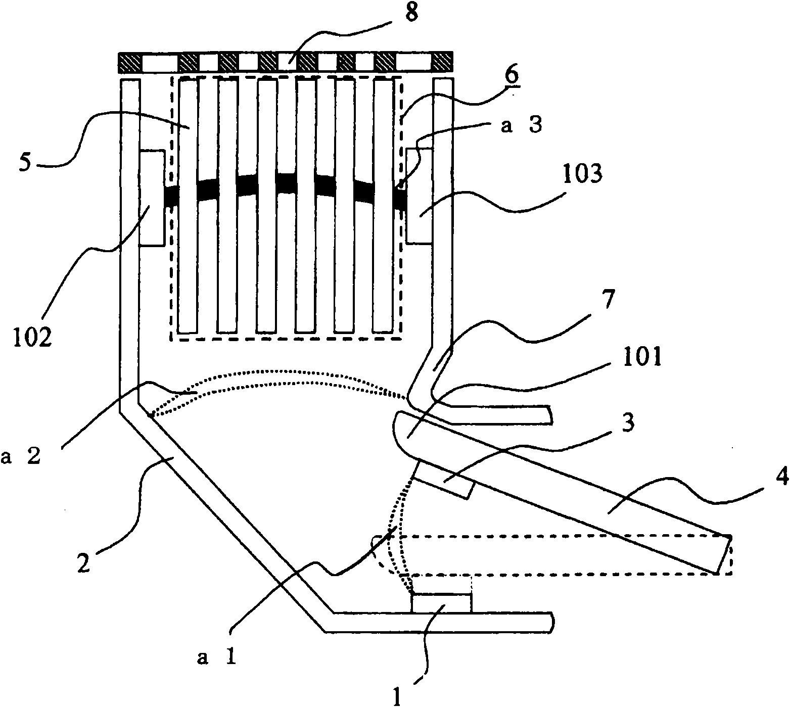
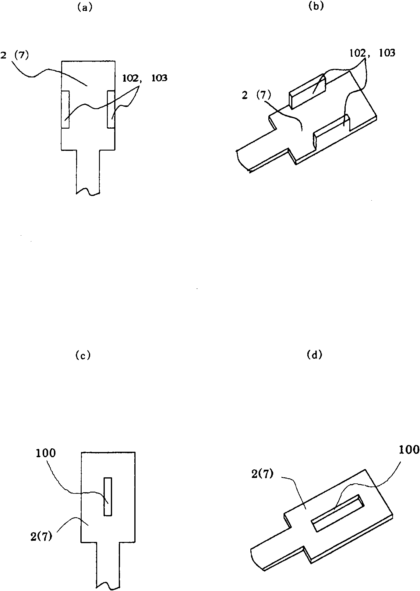
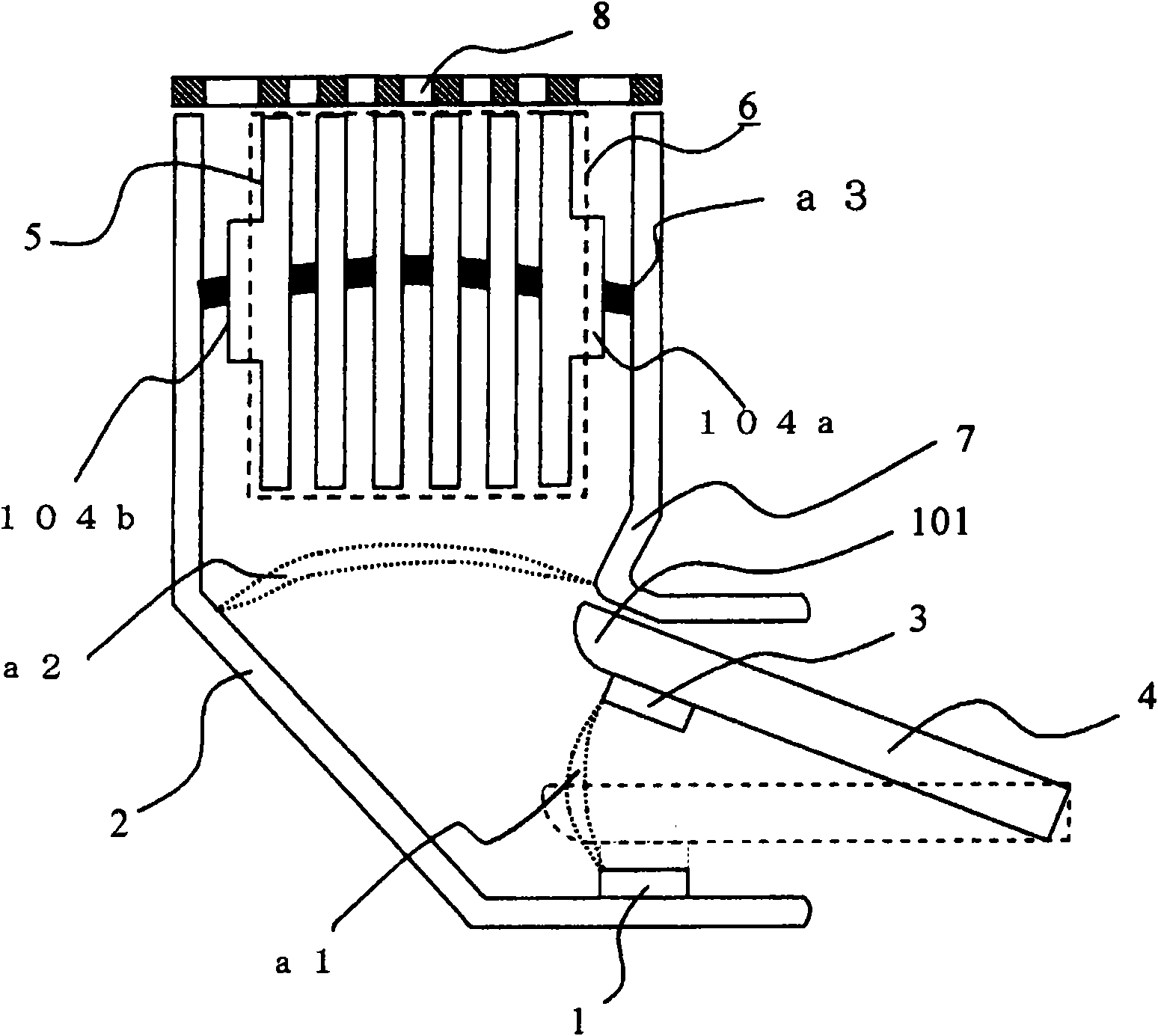
The present invention provides a circuit breaker which comprises a fixed contact point (1), a movable contact point (3) contacted or separated from the fixed contact point (1), an extinguishing arc mechanism (6), an arc movable conductor (2) located on a side of the fixed contact point for leading the arc to the extinguishing arc mechanism (6), and an arc movable conductor (7) located on a side of the movable contact point. The extinguishing arc mechanism (6) is formed by arranging a plurality of extinguishing arc plates (5), the extinguishing arc plates (5) switch and extinguishing arc generated between the fixed contact point (1) and the movable contact point (3) when the movable contact point (3) is separated, the arc movable conducts (2, 7) are opposite to the extinguishing arc plates by spacing preset clearance respectively. An electric field intensification part is arranged on any one or both side of the relative face of the arc movable conducts (2, 7) and the extinguishing arc plate (5) on external side.
Description
Technical field [0001] The present invention relates to a circuit breaker such as a circuit breaker for wiring or a leakage circuit breaker, and more particularly to a circuit breaker capable of improving the current limiting performance of suppressing overcurrent by improving the arc maintenance performance of the arc extinguishing plate in an arc extinguishing chamber In the circuit breaker, the arc extinguishing chamber has an arc moving conductor for moving an arc to a plurality of overlapping arc extinguishing plates as an arc extinguishing device. Background technique [0002] In recent years, the increase in capacity and space saving of low-voltage wiring equipment require miniaturization of the external dimensions of wiring circuit breakers and earth leakage circuit breakers. It is a subject of miniaturization to improve the current-limiting performance that suppresses overcurrent to a low level. In the event of an accident, etc., when the overcurrent is interrupted, t...
Claims
Login to View More Application Information
Patent Timeline
 Patent Type & AuthorityApplications(China)
IPC IPC(8): H01H9/34H01H73/18
Inventor小仓健太郎竹内敏惠吉田忠广牧田阳中川淳饭塚贵士
OwnerMITSUBISHI ELECTRIC CORP