Mechanically regulated vaporization pipe

A technology of tools and sections, applied in the field of vaporization tools and tobacco pipes, can solve the problems of increased complexity of flame filters, cost and safety issues, etc.

Inactive Publication Date: 2010-01-13
ROCK SCI INTELLECTUAL
View PDF6 Cites 9 Cited by
  • Summary
  • Abstract
  • Description
  • Claims
  • Application Information

AI Technical Summary

Problems solved by technology

Flame filters end up adding complexity, expense,

Method used


Image

  • Mechanically regulated vaporization pipe
  • Mechanically regulated vaporization pipe
  • Mechanically regulated vaporization pipe

Examples


Embodiment Construction

[0033] In the following description, for purposes of explanation, numerous specific details are set forth in order to provide a thorough understanding of the invention. It is, however, evident that the invention may be practiced without these specific details.

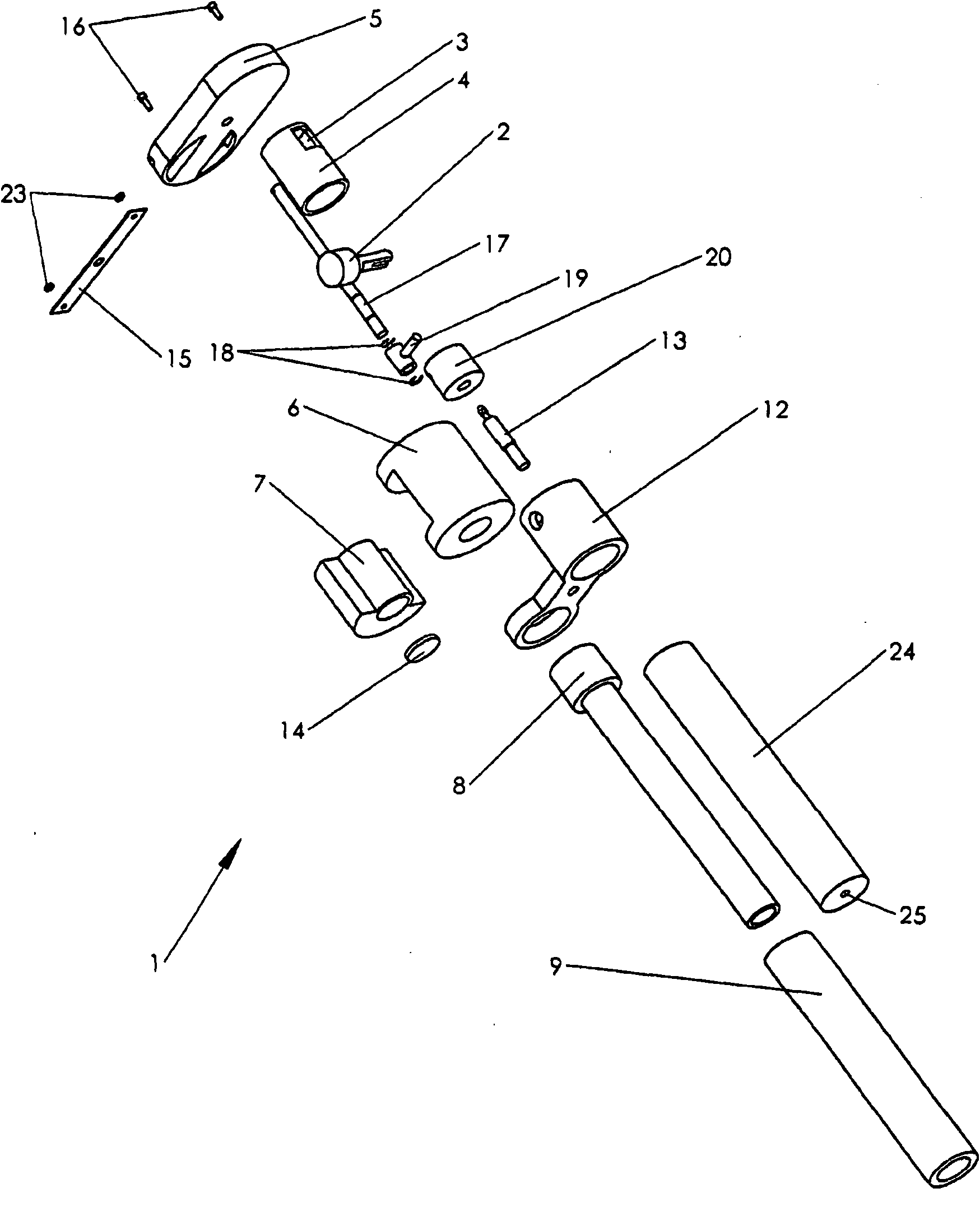
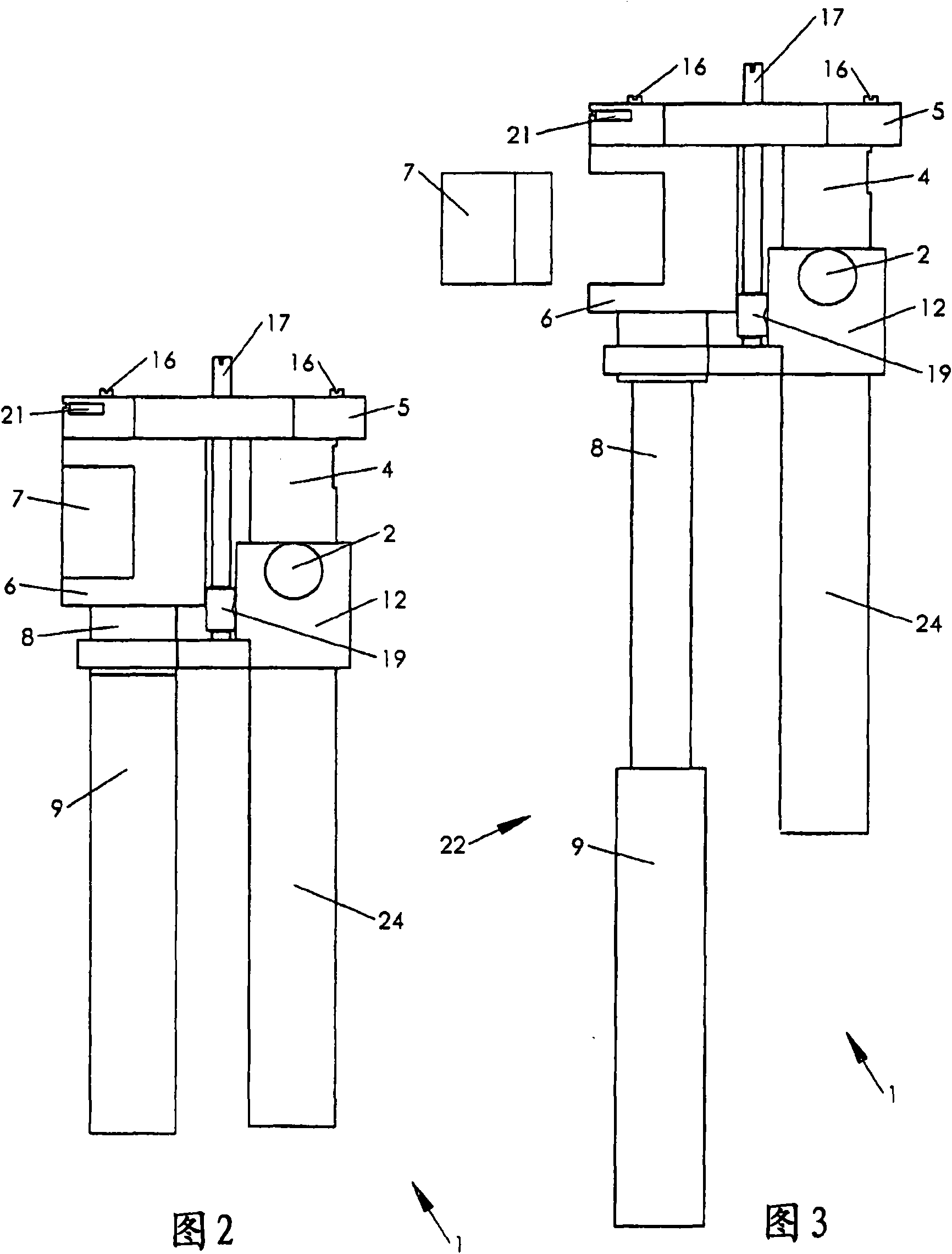
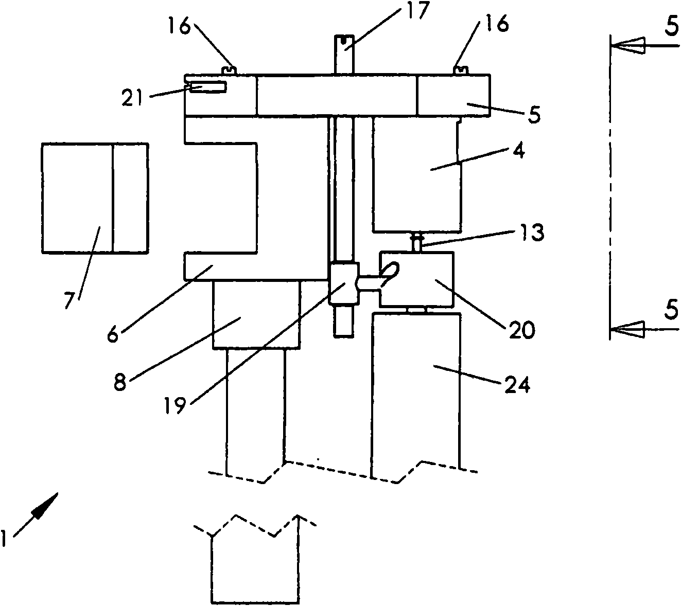
[0034] One embodiment of the present invention is in Figure 1-9 A vaporization tool generally identified by 1 in . A fuel container 24 containing fuel (eg, butane, propane) is connected to the valve assembly 13 to regulate fuel output. The conditioned fuel is combusted in the heating chamber 4 to generate heat. The temperature control inlet 5 (TCI) is in heat exchange contact with the heating chamber 4 but not in fluid contact therewith. The operator is provided with a retractable mouthpiece 22 which allows air to be inhaled. Intake air is heated as it is drawn through the FHAIC 5 . The heated air is then drawn through the smokeable material chamber 10 . The heated air and vaporized components travel through the...


PUM


Abstract

A portable vaporization implement, comprising: a tubular section having a hollow interior, an air intake, and an output orifice; a smoking material chamber that is within said hollow interior and that is in fluid contact with said air intake and said output orifice, and is positioned generally in between said air intake and said output orifice, wherein desired components of a smokable substance may be vaporized; and a purely mechanical means for automatically regulating the amount of heat entering said smoking material chamber, whereby the temperature within said smoking material chamber stays within the vaporization range of said smokable substance, wherein said mechanical means allows unimpeded inhalation by the user.

Description

technical field [0001] The present invention relates generally to smoking implements, such as pipes, and more particularly to vaporizing implements, pipes, etc., wherein a mechanism is provided for converting an ignitable smoking The temperature of the suction material is kept within its vaporization range. Background technique [0002] Tobacco or other herbs are usually smoked by burning and inhaling the combustion smoke and fumes. Smoking implements are generally known. A common smoking implement is called a pipe. In a traditional pipe, tobacco or other lit smoking substance is burned to produce smoke for human consumption. The benefits of traditional pipes include simple construction, ease of use, compactness for easy transport, and low cost. [0003] In recent years, there has been interest in "vaporization" technology, in which smokable material is carefully heated to allow the release of the desired aroma and psychoactive ingredients, and to minimize combustion. V...

Claims


Application Information

Patent Timeline
IPC IPC(8): A24F47/00A24F1/00A24F42/10A24F42/60
CPCA61M11/041A24F47/008A61M15/06A24F47/006A61M2011/048A61M11/048A61M11/042A24F42/10A24F42/60
Inventor M·马尼翁
Owner ROCK SCI INTELLECTUAL
Why Eureka
Try Eureka