Tensioner

A technology for tensioners and shaft components, applied to belts/chains/gears, mechanical equipment, transmissions, etc., which can solve problems such as unstable forward and backward movement and unstable rotation of the propulsion shaft 130

Active Publication Date: 2012-10-24
NHK SPRING CO LTD
View PDF4 Cites 0 Cited by
  • Summary
  • Abstract
  • Description
  • Claims
  • Application Information

AI Technical Summary

Problems solved by technology

[0012] exist Figure 24 and Figure 25 In the shown tensioner 100, there is a problem that the rotating shaft 120 that is biased by the biasing spring 150 rotates slippingly or rotates slightly in the forward and reverse direction. Problem with propulsion shaft 130 making unstable back and forth motion

Method used


Image

  • Tensioner
  • Tensioner
  • Tensioner

Examples


Embodiment Construction

[0058] Hereinafter, the present invention will be specifically described with reference to the illustrated embodiments. In addition, in each embodiment, for the same components, the labels correspond to the same symbols.

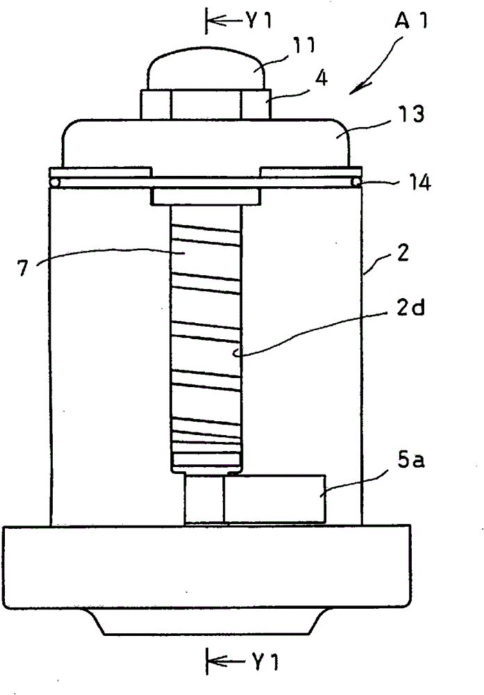
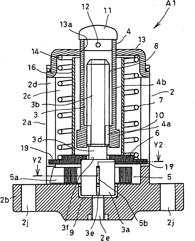
[0059] Figure 1 to Figure 4 The tensioner A1 of the first embodiment of the present invention is shown. The tensioner A1 includes a housing 2 , a first shaft member 3 , a second shaft member 4 , an urging spring 5 , a friction member 6 , and an elastic member 7 .

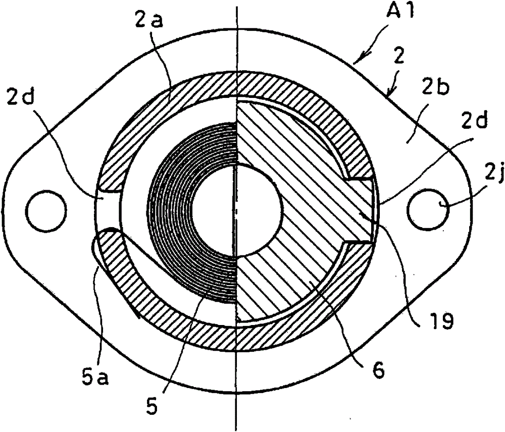
[0060] The housing 2 includes a main body portion 2a and a flange portion 2b. The flange portion 2b extends in a direction perpendicular to the axial direction, and the main body portion 2a extends in the axial direction from the side of the flange portion 2b. The main body part 2a is formed with the accommodation hole 2c. The front end portion of the housing hole 2c is opened, and the assembly of the first shaft member 3, the second shaft member 4, the urging spring 5, the friction member 6,...


PUM


Abstract

A tensioner in which a second shaft member is stably propelled.A first shaft member (3) and a second shaft member (4), which are connected by screw sections (8, 10), and an urging spring (5) for urging the first shaft member (3) in one direction are received in a case (2). Rotation of the second shaft member (4) is restrained, and rotational urging force of the urging spring (5) is converted intopropelling force of the second shaft member (4). The first shaft member (3) is rotated with its shaft end portion directly or indirectly in contact with the case (2). A friction member (6) for generating frictional force between itself and the first shaft member (3) is provided so as to be directly or indirectly in contact with the first shaft member (3). An elastic member (7) for producing urging force so that the shaft end portion of the first shaft member (3) is in contact with the case (2) is provided so as to be in contact with the friction member (6). The friction member (6) is restrained from rotation.

Description

technical field [0001] The present invention relates to a tensioner for maintaining constant tension in an endless (endless) belt or chain. Background technique [0002] The tensioner has the following functions, that is, to press the timing chain or timing belt used in automobile engines with a specified force, and to keep the tension constant when the timing chain or timing belt is extended or slack. [0003] Figure 23 A state in which the tensioner 100 is attached to an automobile engine body 200 is shown. A pair of cam sprockets 210 , 210 and a crank sprocket 220 are disposed inside the engine main body 200 , and a timing chain 230 is endlessly stretched between the sprockets 210 , 210 , and 220 . On the movement path of the timing chain 230 , a chain guide 240 is arranged to be swingable, and the timing chain 230 slides on the chain guide 240 . A mounting surface 250 is formed on the engine main body 200 , and the tensioner 100 is fixed to the mounting surface 250 by...

Claims


Application Information

Patent Timeline
Patent Type & Authority Patents(China)
IPC IPC(8): F16H7/08
CPCF16H7/0831F16H2007/081
Inventor 小林贵雄天野种平高桥郁臣井上史久伊藤隆广
Owner NHK SPRING CO LTD
Why Eureka
Try Eureka