Claw anchoring barbell

A barbell and handle technology, applied to dumbbells, heavy objects, etc., can solve problems such as hidden dangers, inconvenience, smashed property, etc., and achieve the effect of eliminating hidden dangers

Inactive Publication Date: 2010-01-20
CHENGDU JUNFENG TECH DEV
View PDF0 Cites 4 Cited by
  • Summary
  • Abstract
  • Description
  • Claims
  • Application Information

AI Technical Summary

Problems solved by technology

Once the weight is out of the handle, there will be situations of injuring people or property, which is a safety hazard for barbell sports
[0004] 2. Since the in...

Method used


Image

  • Claw anchoring barbell
  • Claw anchoring barbell

Examples


Embodiment Construction

[0014] The present invention will be further described below in conjunction with the accompanying drawings and embodiments.

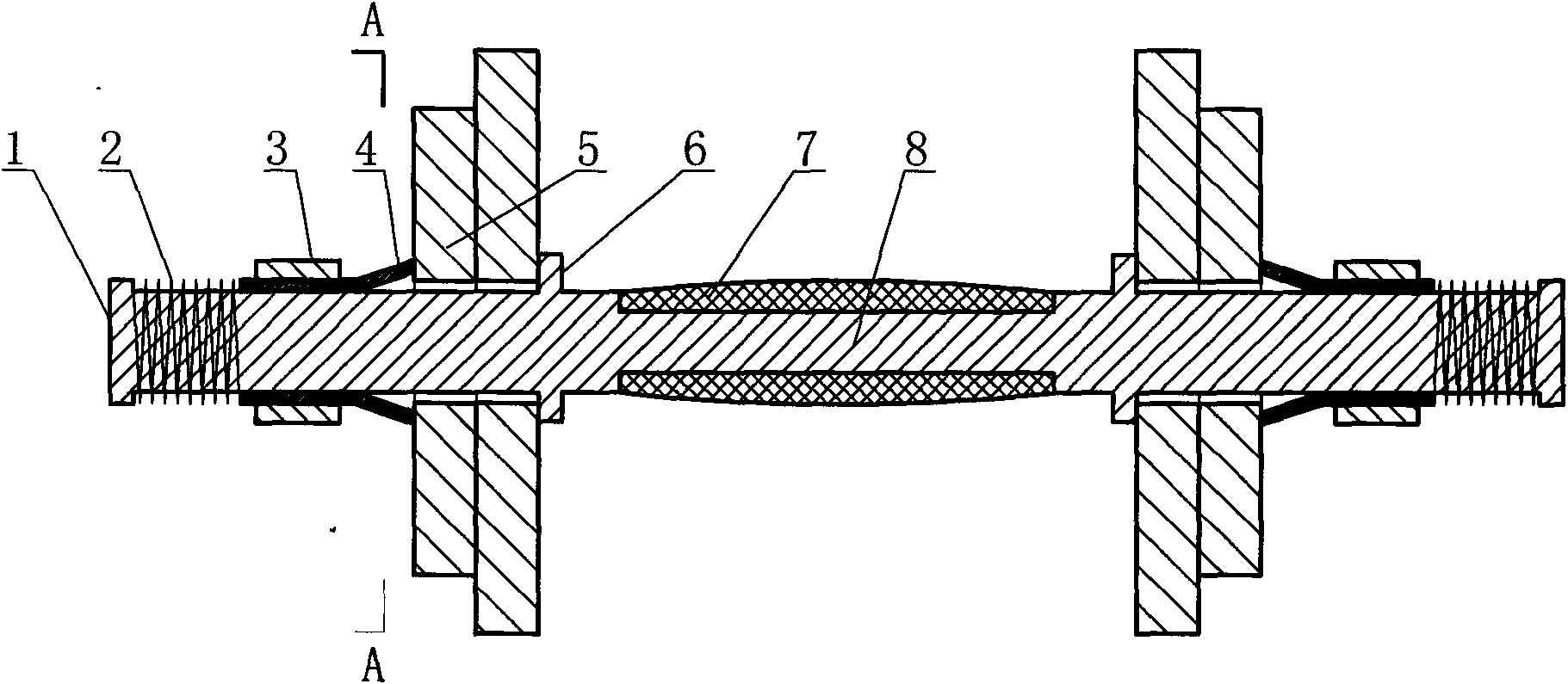
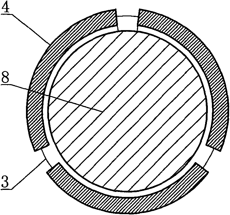
[0015] Claw-anchor barbell is made of circlip edge 1, spring 2, sliding sleeve 3, chuck tube 4, weight disc 5, fixed ring 6, anti-slip sleeve 7, handle 8 and deformation seam 9. The anti-slip cover 7 is a rubber cover whose outer surface is curved, and the anti-slip cover 7 is set on the groove in the handle 8 middle part. The handle 8 is cylindrical, and the two ends of the handle 8 respectively have a circle of circlip edges 1 protruding from the side of the handle 8 . On the handle 8, there are two annular fixed rings 6 integral with the handle 8, and the distance between each fixed ring 6 and the two ends of the handle 8 is respectively 1 / 4 of the length of the handle 8, and the clip The disc cylinder 4 is sleeved on the handle 8 and is in a moving relationship with the handle 8 . The weight plate 5 is set on the handle 8 and the radius difference...


PUM


Abstract

The invention relates to a sport facility, in particular to a claw anchoring barbell which is constructed by snap spring edges, a spring, a sliding sleeve, a cartridge barrel, a weight tray, fixing rings, an anti-sliding sleeve, a grab handle and a deformed seam. The grab handle is of column shape, two ends of the grab handle are respectively provided with a snap spring edge protruding out of the side of the grab handle. The grab handle is provided with two annular fixing rings integrated with the grab handle, and the cartridge barrel sheathed at the grab handle and in dynamic match relation with the grab handle. The weight tray is sheathed on the grab handle and the difference between the central hole of the weight tray and the radius of the grab handle is greater than the thickness of the cartridge barrel. The cartridge barrel is positioned at the outer end of the weight tray, and the spring is sheathed on the grab handle between the cartridge barrel and the snap spring edges. The cartridge barrel is composed of the outer cylinder and the inner cone face thereof. The invention eliminates the potential safety hazard caused by slipping of the weight tray in the motion of the barbell.

Description

technical field [0001] The invention relates to a sports apparatus, in particular to a claw-anchor barbell. Background technique [0002] Existing barbells are usually made of lead-filled handles with threads at both ends and weights screwed on the two ends of the handles. This has two disadvantages: [0003] 1. Because in the process of lifting and lowering the barbell, the human hand will exert a certain torque on the barbell, and because there is a big difference between the inertia of the barbell as a whole and the inertia of the handle directly subjected to torque, it often occurs A condition in which the weight rotates counterclockwise due to inertia and disengages from the handle. Once the weight is out of the handle, there will be a situation of injuring people or damaging property, which is a safety hazard for barbell sports. [0004] 2. Since the installation and removal of the weight plate requires the weight coil to be rotated around the handle for many turns,...

Claims


Application Information

Patent Timeline
IPC IPC(8): A63B21/075
Inventor 佘玲
Owner CHENGDU JUNFENG TECH DEV
Why Eureka
Try Eureka