Coarse alignment method for fiber optic gyro strapdown inertial navigation system based on single axis rotation

A strapdown inertial navigation and fiber optic gyroscope technology, applied in the field of measurement, can solve the problems of poor alignment effect and poor alignment performance

Inactive Publication Date: 2010-01-20
HARBIN ENG UNIV
View PDF0 Cites 39 Cited by
  • Summary
  • Abstract
  • Description
  • Claims
  • Application Information

AI Technical Summary

Problems solved by technology

Among them, the analytical method can meet the requirements for coarse alignment on the static base condition; but if the carrier is in the process of swaying, the angular velocity measured by the gyroscope is no longer the angular velocity of the earth's rotation. If the carrier has heave, surge, and sway Or when the random interference is relatively large, the accelerometer does not measure the acceleration of gravity, and the effect of coarse alignment will become worse at this time, so the analytical method has great limitations in practical applications
The horizontal second-order leveling + azimuth estimation method is not only suitable for the rough alignment of the static base, but also for the rough alignment process under the swing base, and has a certain anti-interference ability, but when the carrier has heave, surge, and horizontal When there is oscillation or high-frequency random interference, the alignment performance will be greatly reduced

Method used


Image

  • Coarse alignment method for fiber optic gyro strapdown inertial navigation system based on single axis rotation
  • Coarse alignment method for fiber optic gyro strapdown inertial navigation system based on single axis rotation
  • Coarse alignment method for fiber optic gyro strapdown inertial navigation system based on single axis rotation

Examples


Embodiment Construction

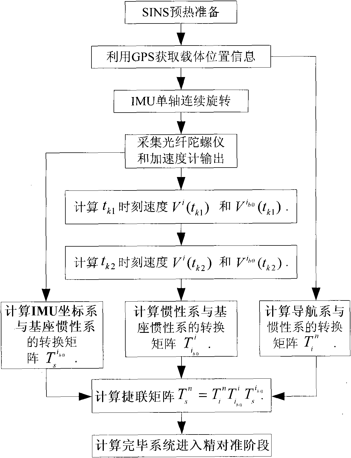
[0075] The specific embodiments of the present invention will be described in detail below with reference to the accompanying drawings:

[0076] (1) Determine the initial position parameters of the carrier through GPS and bind them to the navigation computer;

[0077] (2) The strapdown inertial navigation system prepares for warm-up, collects the data output by the fiber optic gyroscope and the quartz accelerometer and processes the data;

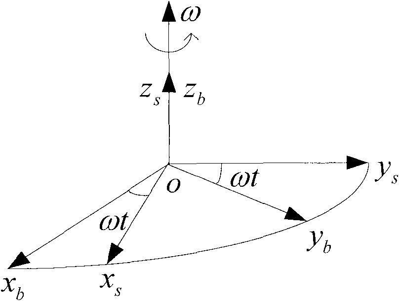
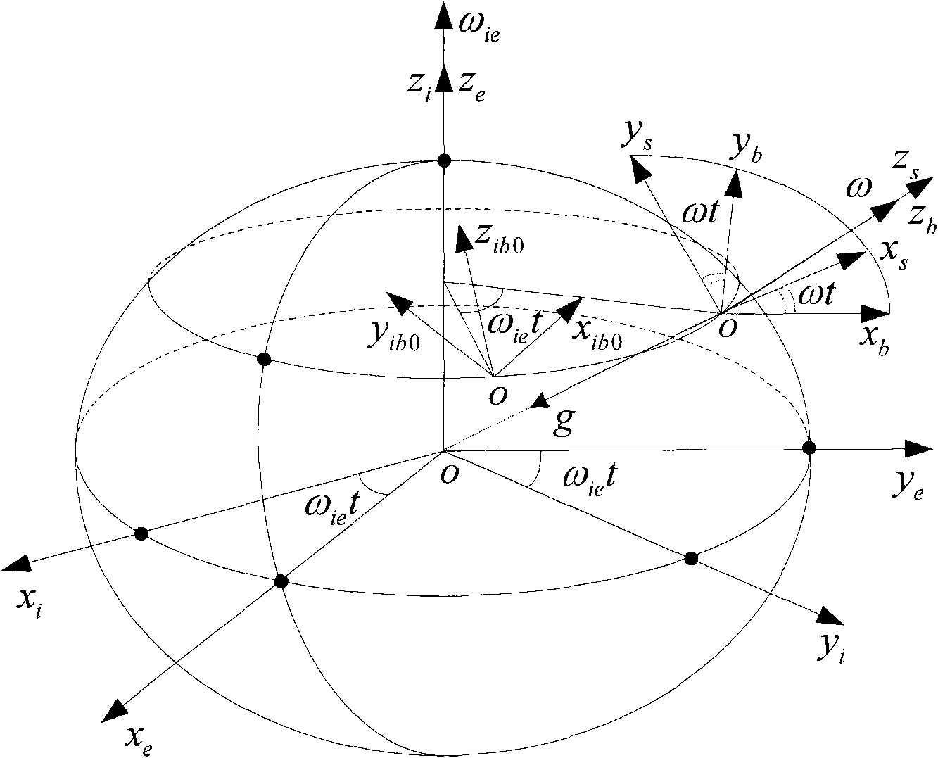
[0078] (3) According to the mutual positional relationship of the coordinate system (as attached image 3 ) Determine the conversion matrix T between the navigation coordinate system and the inertial coordinate system i n .

[0079] Where T e n It is the transformation matrix between the navigation coordinate system n and the earth coordinate system e, which can be determined by the longitude and latitude (L, λ) of the point where the carrier is located.

[0080] T e n = 1 0 0 0 sin L cos L 0 - co...


PUM


Abstract

The invention provides a coarse alignment method for a fiber optic gyro strapdown inertial navigation system based on single axis rotation. The coarse alignment method comprises the following steps: (1) determining initial position parameters of a carrier by a GPS; (2) collecting the data output by a fiber optic gyroscope and a quartz accelerometer and processing the data; (3) determining a transfer matrix Ti<n> of a navigation coordinate system and an inertial coordinate system according to the mutual position relation of the coordinate systems; (4) allowing a single axis of an inertial measurement unit to continuously rotate, setting superposition of an initial time IMU coordinate system s and a carrier coordinates b, then allowing the inertial measurement unit to continuously rotate around a positive direction of an azimuth axis ozb of the carrier coordinate system with an angular velocity Omega=6 degrees/s; (5) determining the relative position relation of the inertial coordinate system and a base inertial coordinate system; and (6) determining an expression of a strapdown matrix after coarse alignment is over according to the calculated relative conversion relation of the coordinate systems calculated in step (3), (4) and (5). The coarse alignment method can help obtain higher coarse alignment precision under a swinging interference condition.

Description

(1) Technical field [0001] The invention relates to a measurement method, in particular to a coarse alignment method of an optical fiber gyroscope strapdown inertial navigation system based on single-axis rotation. (2) Background technology [0002] Strapdown inertial navigation system is based on Newton’s law of relative inertial space, using gyroscopes, accelerometers and other inertial measurement elements to measure the acceleration of sensitive carriers, and then according to the given initial conditions, through the computer to obtain various navigation parameters Because the strapdown system does not have a platform frame and a connected servo mechanism, it simplifies the hardware. Compared with the platform inertial navigation system, it has the advantages of small size, light weight, low cost, and higher reliability. Therefore, it has been more and more widely used. Application, the navigation accuracy of strapdown inertial navigation system depends to a large extent on ...

Claims


Application Information

Patent Timeline
Patent Type & Authority Applications(China)
IPC IPC(8): G01C21/18G01C25/00
Inventor 孙枫孙伟袁俊佳薛媛媛郭真孙巧英胡晓形李国强王琦
Owner HARBIN ENG UNIV
Why Eureka
Try Eureka