Self-alignment method of vehicle strapdown inertial navigation system under moving base

A strapdown inertial navigation and moving base technology, applied in the field of kalman filtering

Active Publication Date: 2019-11-12
HUNAN AEROSPACE ELECTROMECHANICAL EQUIP & SPECIAL MATERIAL INST
View PDF10 Cites 6 Cited by
  • Summary
  • Abstract
  • Description
  • Claims
  • Application Information

AI Technical Summary

Problems solved by technology

[0006]The purpose of the present invention is to propose a self-alignment system for a vehicle-mounted strapdown inertial navigation system under a moving base in view of the situation that the system noise becomes larger under the moving base method, first adopt the solidification method for rough alignment, calculate the rotation angle of the gravitational acceleration vector in the inertial space on the basis that the time can be accurately known, and extract the true north information contained in the direction change of the gravitational acceleration vector in the inertial space, to realize Coarse alignment; then on the basis of rough alignment, use the inertial navigation system error equation and inertial device error equation to construct the kalman filter state equation and measurement equation; finally use the hybrid calibration kalman filter method to estimate the inertial navigation system speed error and position error, attitude error and inertial device error, etc. and correct them to achieve high-precision self-alignment

Method used


Image

  • Self-alignment method of vehicle strapdown inertial navigation system under moving base
  • Self-alignment method of vehicle strapdown inertial navigation system under moving base
  • Self-alignment method of vehicle strapdown inertial navigation system under moving base

Examples


Embodiment Construction

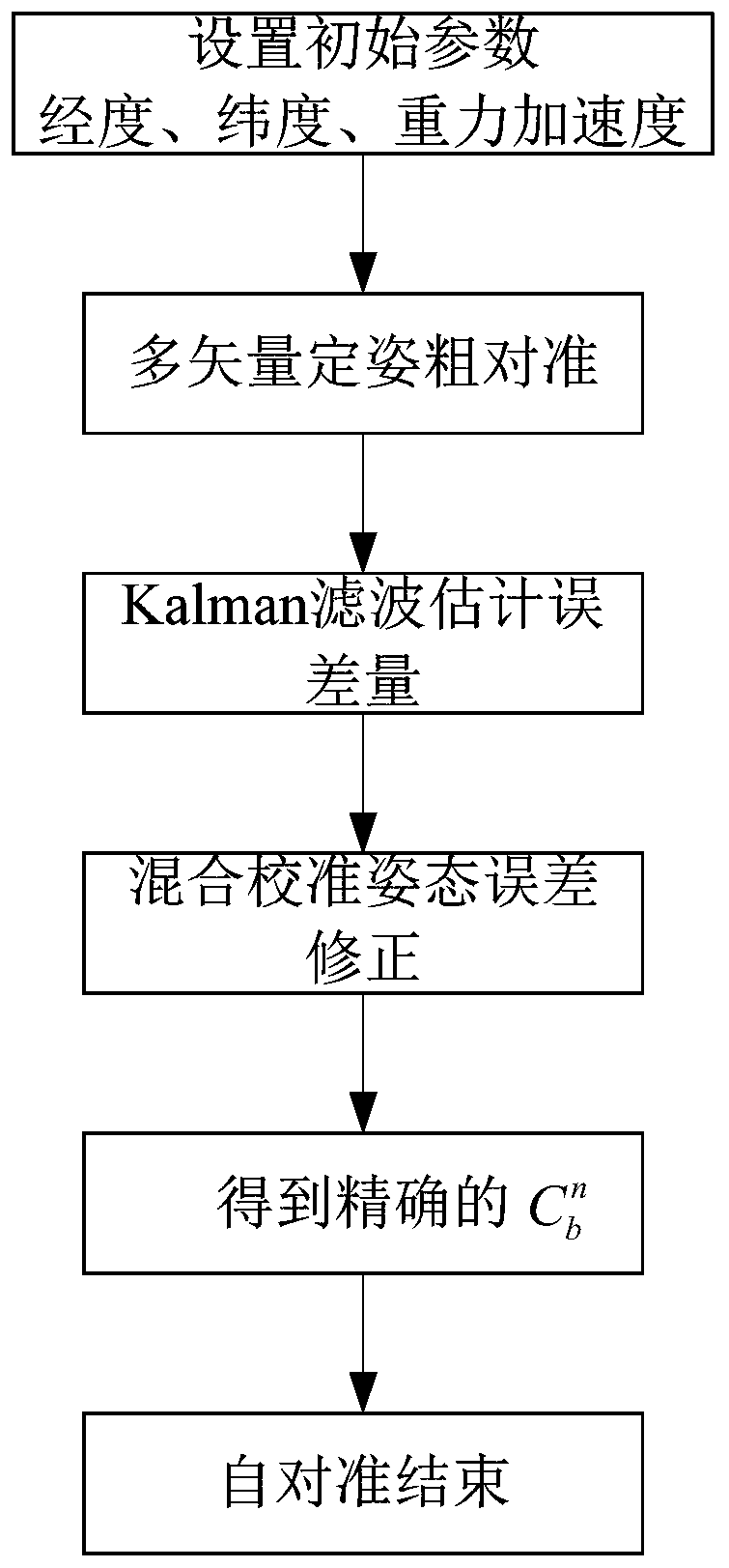
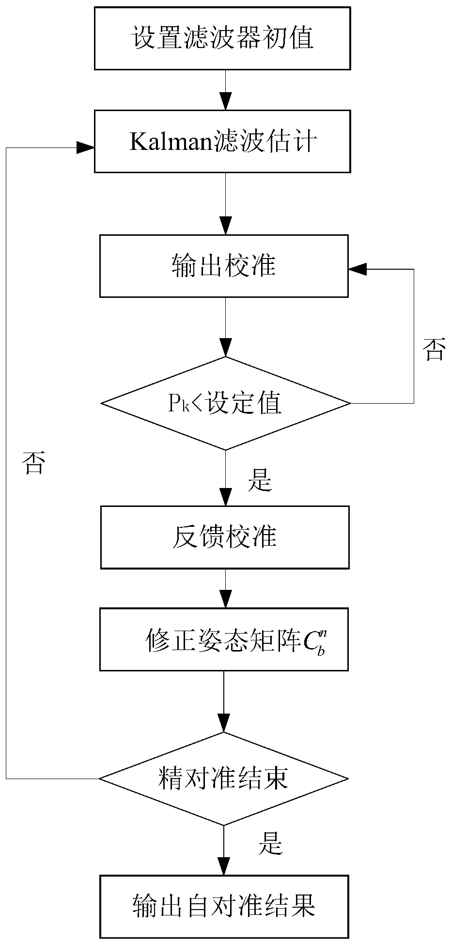
[0077] Combine below figure 1 and figure 2 The specific implementation steps of the present invention are described in detail:

[0078] In the detailed description of the implementation steps below, the coordinate system is defined as follows:

[0079] Earth coordinate system e system: the origin is the center of the earth, the X-axis is located in the equatorial plane, pointing from the center of the earth to the meridian of the point where the carrier is located, the Z-axis is along the direction of the earth's rotation axis, and rotates with the earth's rotation, and the X-axis, Y-axis and Z-axis form The right-handed coordinate system rotates with the rotation of the earth.

[0080] Earth-centered inertial coordinate system i system: Inertial coordinate system refers to a reference coordinate system that is static in space or moves in a straight line at a uniform speed. The origin of the geocentric inertial coordinate system is taken at the center of the earth O e The...


PUM


Abstract

The invention discloses a self-alignment method of a vehicle strapdown inertial navigation system under a moving base. The method comprises the following steps of step 1, obtaining geographic positioninformation of the strapdown inertial navigation system, wherein the geographic position information comprises longitude lambda and latitude gravity acceleration g; step 2, performing coarse alignment by using a multi-vector attitude determination method according to longitude, latitude, gravity acceleration information and inertial device output information by adopting a solidification coordinate system, and obtaining an initial attitude matrix; step 3, constructing a Kalman filtering state equation and a measurement equation according to a strapdown inertial system error equation and an inertial device error equation; and step 4, designing a mixed calibration Kalman filtering method to estimate the system error amount and the inertial device error amount and correct the system error amount and the inertial device error amount, so that a fine alignment process is realized, and initial alignment is completed. The self-alignment method of the vehicle strapdown inertial navigation system under the moving base disclosed by the invention has relatively strong anti-interference capability and ensures the self-alignment precision under the condition of the moving base.

Description

technical field [0001] The invention particularly relates to a self-alignment method for a vehicle-mounted strapdown inertial navigation system under a moving base, and relates to the establishment of a kalman filter state space model based on a solidified coordinate system for rough alignment and fine alignment under a moving base and a hybrid calibration method Kalman filter method. The invention is suitable for the self-alignment process of other carriers with the same working conditions in vehicle environments such as vehicle body shaking, people going up and down, natural interference, and vehicle engine startup. Background technique [0002] For the strapdown inertial navigation system (strapdown inertial navigation system), initial alignment is an important prerequisite for carrying out navigation tasks, and its purpose is to establish an accurate initial coordinate reference, that is, the attitude matrix of the carrier system relative to the navigation system. Align...

Claims


Application Information

Patent Timeline
Patent Type & Authority Applications(China)
IPC IPC(8): G01C25/00
CPCG01C25/005
Inventor 吴志洁
Owner HUNAN AEROSPACE ELECTROMECHANICAL EQUIP & SPECIAL MATERIAL INST
Why Eureka
Try Eureka