Method for controlling motion mechanisms used on laser cutting equipment

A motion mechanism and laser cutting technology, applied in laser welding equipment, electric controllers, controllers with specific characteristics, etc., can solve problems such as vibration or howling, motion mechanism deviation, and reduce system indicators to achieve a high degree of automation Effect

Inactive Publication Date: 2010-01-20
深圳市华德激光技术有限公司
View PDF0 Cites 4 Cited by
  • Summary
  • Abstract
  • Description
  • Claims
  • Application Information

AI Technical Summary

Problems solved by technology

[0003] The present invention provides a control method for the motion mechanism on the laser cutting equipment to solve the problems caused by the improvement of the system noise, the rigidity of the motion mechanism, the processing accuracy of the parts, the moving parts, etc. The friction coefficient, assembly error, design error and other factors lead to large deviation, vibration or howling of the motion mechanism and the technical problem that the system index must be reduced

Method used


Image

  • Method for controlling motion mechanisms used on laser cutting equipment
  • Method for controlling motion mechanisms used on laser cutting equipment
  • Method for controlling motion mechanisms used on laser cutting equipment

Examples


Embodiment Construction

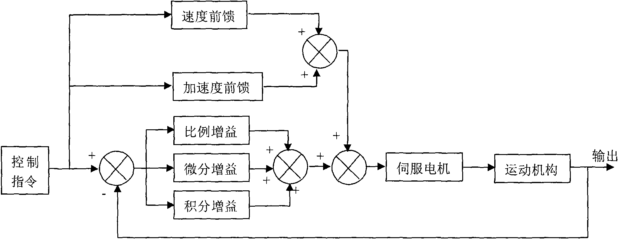
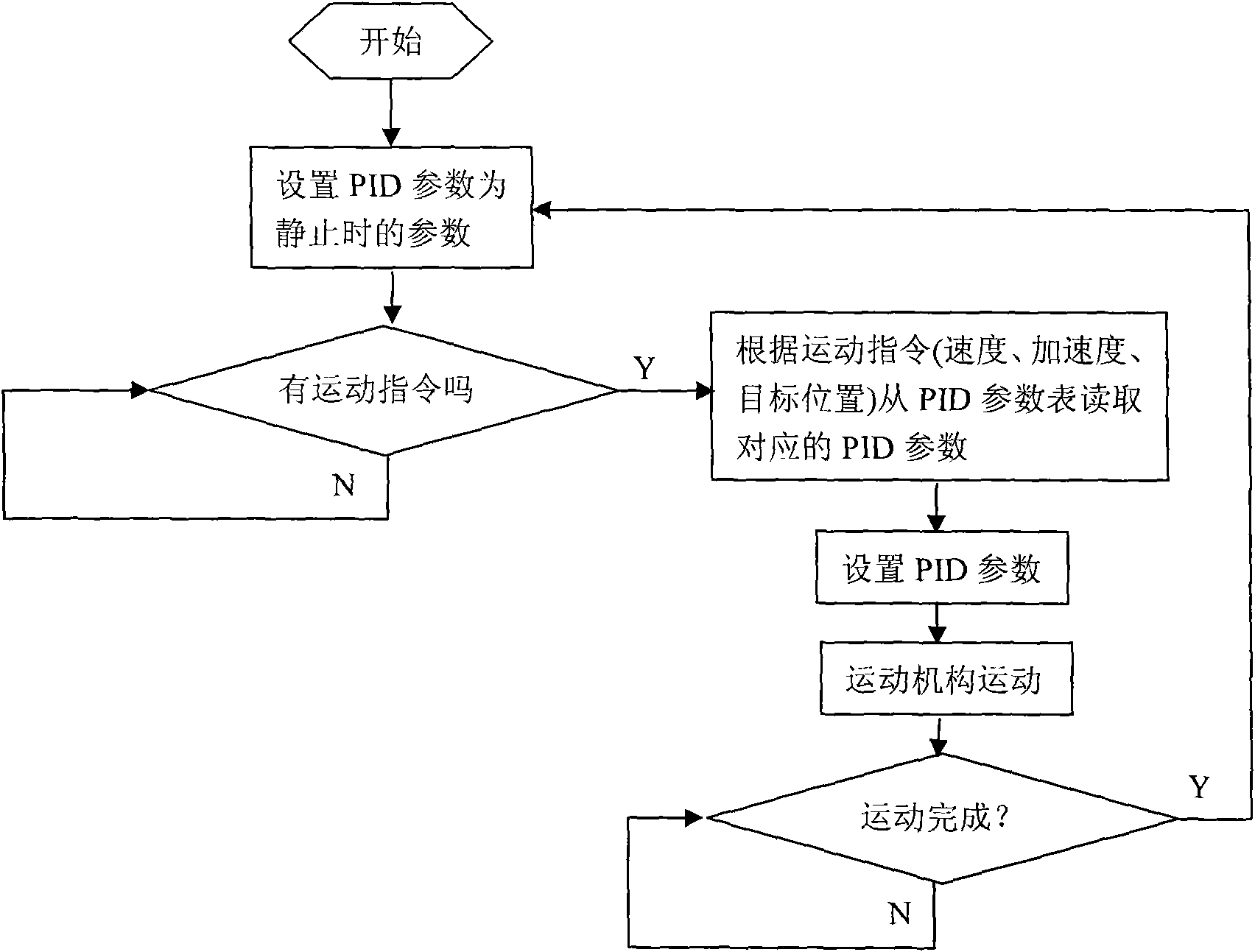
[0019] Such as figure 2 As shown, a control method for a kinematic mechanism on a laser cutting device controls the movement of a kinematic mechanism on a laser cutting device through PID parameters input to a PID controller, including the following steps:

[0020] (1) PID parameters are set to static PID parameters;

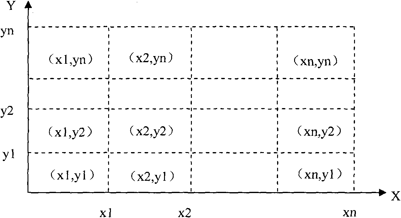
[0021] (2) Judging whether there is a motion command, if there is, the PID parameter is used as the motion PID parameter to control the motion of the motion mechanism, the motion PID parameter is selected from the motion PID parameter database, and then its area is selected according to the location of the motion mechanism Motion PID parameters, the motion PID parameter database stores the regional motion PID parameters of all areas given according to the different plane position areas where the motion mechanism is located; otherwise, continue to judge whether there is a motion command; the plane position area where the motion mechanism is located division as ...


PUM


Abstract

The invention relates to a method for controlling motion mechanisms used on laser cutting equipment. The method comprises the following steps: (1) setting PID parameters as static PID parameters; (2) judging whether a motion instruction exists, changing the PID parameters into kinetic PID parameters and controlling the motion of a motion mechanism if so, otherwise continuing to judge whether the motion instruction exists; and (3) judging whether the motion of the motion mechanism is finished, setting the PID parameters as the static PID parameters again if so, otherwise continuing to judge whether the motion of the motion mechanism is finished. As the PID parameters are divided into the static PID parameters and the kinetic PID parameters according to the motion state of the motion mechanism, the technical problem that system indexes need to be reduced as the prior art uses fixed PID parameters causing the motion mechanism to have large deviation and vibration or squeals.

Description

technical field [0001] The invention relates to a control method for a motion mechanism on laser cutting equipment. Background technique [0002] The existing control methods for the motion mechanism on the laser cutting equipment are generally passed to the PID (PID is the English abbreviation of proportional, integral, and differential differential. It is a special term in control theory, the same below) controller Input a PID parameter to control the movement of the motion mechanism on the laser cutting equipment. The principle of the PID controller is as follows: figure 1 shown. The role of the PID controller is to smooth out the deviation caused by the motion. In an ideal state, by setting a PID parameter (including proportional gain, differential gain, integral gain, speed feedforward gain, acceleration feedforward gain), the following error, positioning accuracy, positioning time and steady-state error of the motion mechanism can be adjusted to the ideal state. Bu...

Claims


Application Information

Patent Timeline
Patent Type & Authority Applications(China)
IPC IPC(8): G05B11/42B23K26/00
Inventor 付学斌程金政雷宇
Owner 深圳市华德激光技术有限公司
Why Eureka
Try Eureka