Magnetic motor manufactured from magnet ring, fixed magnets and closed cavity
A technology for fixing magnets and magnetic rings, applied in the direction of generators/motors, electrical components, etc., can solve problems such as consumption and ecological damage, and achieve the effect of no noise
Inactive Publication Date: 2010-01-27
张洪波
View PDF0 Cites 0 Cited by
- Summary
- Abstract
- Description
- Claims
- Application Information
AI Technical Summary
Problems solved by technology
[0002] Now all power output machines (except electric motors) need to consume visible material energy, and at the same time emit a large amount of heat and pollutants, causing ecological damage, while consuming precious and limited energy on the earth
Method used
View moreImage
Smart ImageViewing Examples

Examples
Embodiment Construction
[0013] The inventor believes that the principle of the present invention should be analyzed repeatedly before implementation, and after fully understanding all the contents, the mechanical engineer should design all the mechanical accessories and permanent magnet parts according to the mechanical position of the technical product applied to the equipment. , and then assemble according to its design is the preferred way.
Login to View More PUM
 Abstract
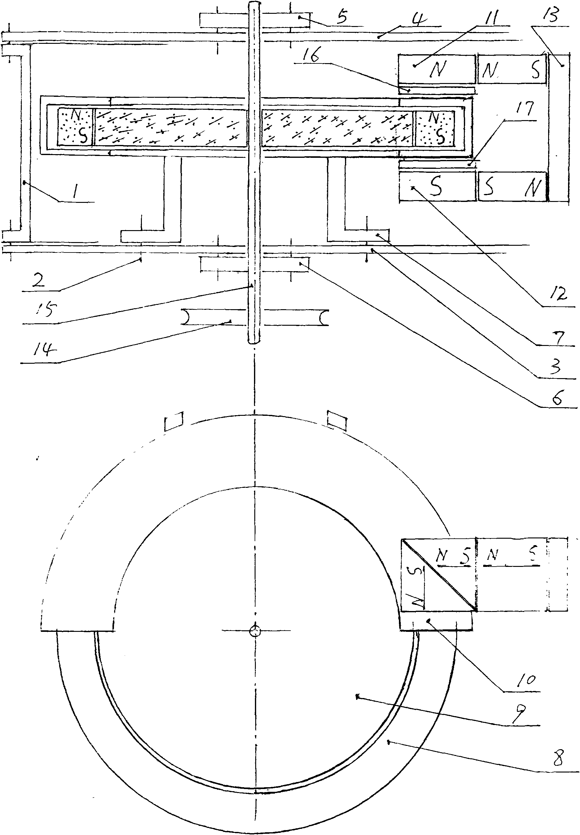
The invention relates to a magnetic motor manufactured from a magnet ring, fixed magnets and a closed cavity, which belongs to a magnetic-kinetic energy conversion machine. All prior power output machines (except motors) need to consume visible energy and simultaneously exhaust a large amount of heat and a large number of pollutants to damage earth ecology. The invention designs and manufactures the magnetic motor manufactured from the magnet ring, the fixed magnets and the closed cavity. The magnetic motor can perpetually output power without consuming the visible material energy to supply other machines for operation, and the magnetic motor does not release the heat and pollutants. The magnetic motor mainly comprises a machine shell, universal bolts, a lower cover board, an upper cover board, an upper bearing component, a lower bearing component, a support, the magnet ring, a circular plastic board, the closed cavity, an upper fixed magnet, a lower fixed magnet, a concentrating flux plate, a power output wheel, a crankshaft, an upper partition board, a lower partition board and the like, and can be widely applied to all equipment and machines which need the power.
Description
Technical field: [0001] It is a magnetic kinetic energy conversion machine. Background technique: [0002] Now all power output machines (except electric motors) need to consume visible material energy, discharge a large amount of heat and pollutants, cause ecological damage, and consume precious and limited energy on the earth. Invention content: [0003] The present invention will design a kind of magnetic motor made with magnetic ring and fixed magnet and closed chamber exactly. [0004] Realize that the technical scheme that the present invention adopts is: at first will refer to the accompanying description figure 1 , design and manufacture a magnetic ring 8, a round plastic plate (or other non-magnetic materials) 9, an upper fixed magnet 11, a lower fixed magnet 12, an upper partition 16, a lower partition 17, a closed cavity 10, a casing 1, Lower cover plate 3, upper cover plate 4, bracket 7, crankshaft 15, power output wheel 14, upper bearing assembly 5, lower be...
Claims
Login to View More Application Information
Patent Timeline
 IPC IPC(8): H02N11/00
Inventor 张洪波
Owner 张洪波
Features
- Generate Ideas
- Intellectual Property
- Life Sciences
- Materials
- Tech Scout
- Unparalleled Data Quality
- Higher Quality Content
- 60% Fewer Hallucinations
Learn More Browse by: Latest US Patents, China's latest patents, Technical Efficacy Thesaurus, Application Domain, Technology Topic, Popular Technical Reports.
© 2025 PatSnap. All rights reserved.Legal|Privacy policy|Modern Slavery Act Transparency Statement|Sitemap|About US| Contact US: help@patsnap.com