Method and device for monitoring multiple mirror arrays in an illumination system of a microlithographic projection exposure apparatus

A lighting system and microlithography technology, applied in the field of lighting systems, can solve the problems of large volume of beam deflection elements, affecting effective work, and large number of mirror elements

Active Publication Date: 2010-01-27
CARL ZEISS SMT GMBH
View PDF5 Cites 25 Cited by
  • Summary
  • Abstract
  • Description
  • Claims
  • Application Information

AI Technical Summary

Benefits of technology

This technology allows an imaging lens (such as those made up of multiple reflective surfaces) to measure its properties without interference between measurements taken with another measurement tool. It also includes a special type of sensor called a scanning laser diode detector(SLFD), which helps detect any deviations in the image being formed due to imperfections within the lenses themselves. Additionally, there may exist devices like microscopes that control how much material needs to penetrate into them while they work through their own process. These technical improvements allow for precise monitoring and correction of these processes throughout manufacturing operations.

Problems solved by technology

Technological Problem: The technical problem addressed in this patents relates to improving the accuracy and efficiency of microscopic photolithographic processes while minimizing losses during image quality control procedures. Specifically, there has been proposed methods involving varying the angles at which certain parts of the projected images pass through optical devices called multiple reflection element arrays. However, these techniques have limitations because they require precise knowledge of how each component's movement affects its final outcome. Additionally, current methods involve extracting significant amounts of energy from the reflected radiation, making them difficult to operate efficiently without damaging sensitive areas within the system.

Method used


Image

  • Method and device for monitoring multiple mirror arrays in an illumination system of a microlithographic projection exposure apparatus
  • Method and device for monitoring multiple mirror arrays in an illumination system of a microlithographic projection exposure apparatus
  • Method and device for monitoring multiple mirror arrays in an illumination system of a microlithographic projection exposure apparatus

Examples


Embodiment Construction

[0040] 1. Structure of projection exposure equipment

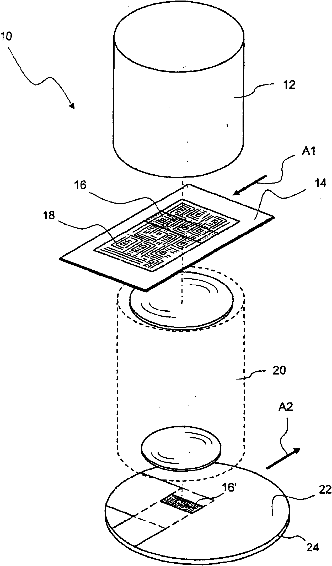
[0041] figure 1A perspective view of a projection exposure apparatus 10 is shown very schematically, which is suitable for the lithographic production of microstructured components. The projection exposure system 10 comprises an illumination system 12 which illuminates a narrow, in the exemplary embodiment shown, rectangular illumination field 16 on a mask 14 arranged in a so-called mask plane. The lighting system 12 contains light sources by means of which projected light can be generated. Commonly used light sources are, for example, excimer lasers with laser media KrF, ArF or F2, with which projection light with a wavelength of 248 nm, 193 nm or 157 nm can be generated respectively. The structures 18 on the mask 14 within the illuminated region 16 are imaged onto the photosensitive layer 22 by means of the projection objective 20 . The photosensitive layer 22 , which can be, for example, a photoresist here, is applie...


PUM


Abstract

The invention relates to an illumination system (12) of a microlithographic projection exposure apparatus (10), comprising a pupil surface and a substantially planar arrangement of beam deflecting elements (28) which can preferably be triggered in an individual manner and are used for variably illuminating the pupil surface. Each beam deflecting element (28) allows a projection light beam (32) that is incident thereon to be deflected in accordance with a control signal which is applied to the beam deflecting element (28). A measuring illumination device (54, 56, 58, 60; 88; 90; 98) directs a measuring light beam (36) that is independent from the projection light beams (32) onto a beam deflecting element (28). A detector device detects the measuring light beam (38) after the latter has been deflected on the beam deflecting element (28). An evaluation unit determines the deflection of the projection light beam (32) from the test signals supplied by the detector device.

Description


Claims


Application Information

Patent Timeline
Owner CARL ZEISS SMT GMBH
Why Eureka
Try Eureka