Spinning device and spinning nozzle assembly used for the spinning device

A spinning device and component technology, applied in the field of spinning nozzle components, can solve the problems of inability to compensate for material fatigue, large operating force, etc., and achieve the effects of avoiding overload, avoiding excessive adjustment of spring preload, and reliable sealing

Active Publication Date: 2010-02-03
OERLIKON TEXTILE GMBH & CO KG
View PDF2 Cites 17 Cited by
  • Summary
  • Abstract
  • Description
  • Claims
  • Application Information

AI Technical Summary

Problems solved by technology

In principle, however, this spinning device has the disadvantage that the clamping of the seal between the melt inlet and the melt connection is only achieved by the connecting force generated by screwing
As such,

Method used


Image

  • Spinning device and spinning nozzle assembly used for the spinning device
  • Spinning device and spinning nozzle assembly used for the spinning device
  • Spinning device and spinning nozzle assembly used for the spinning device

Examples


Embodiment Construction

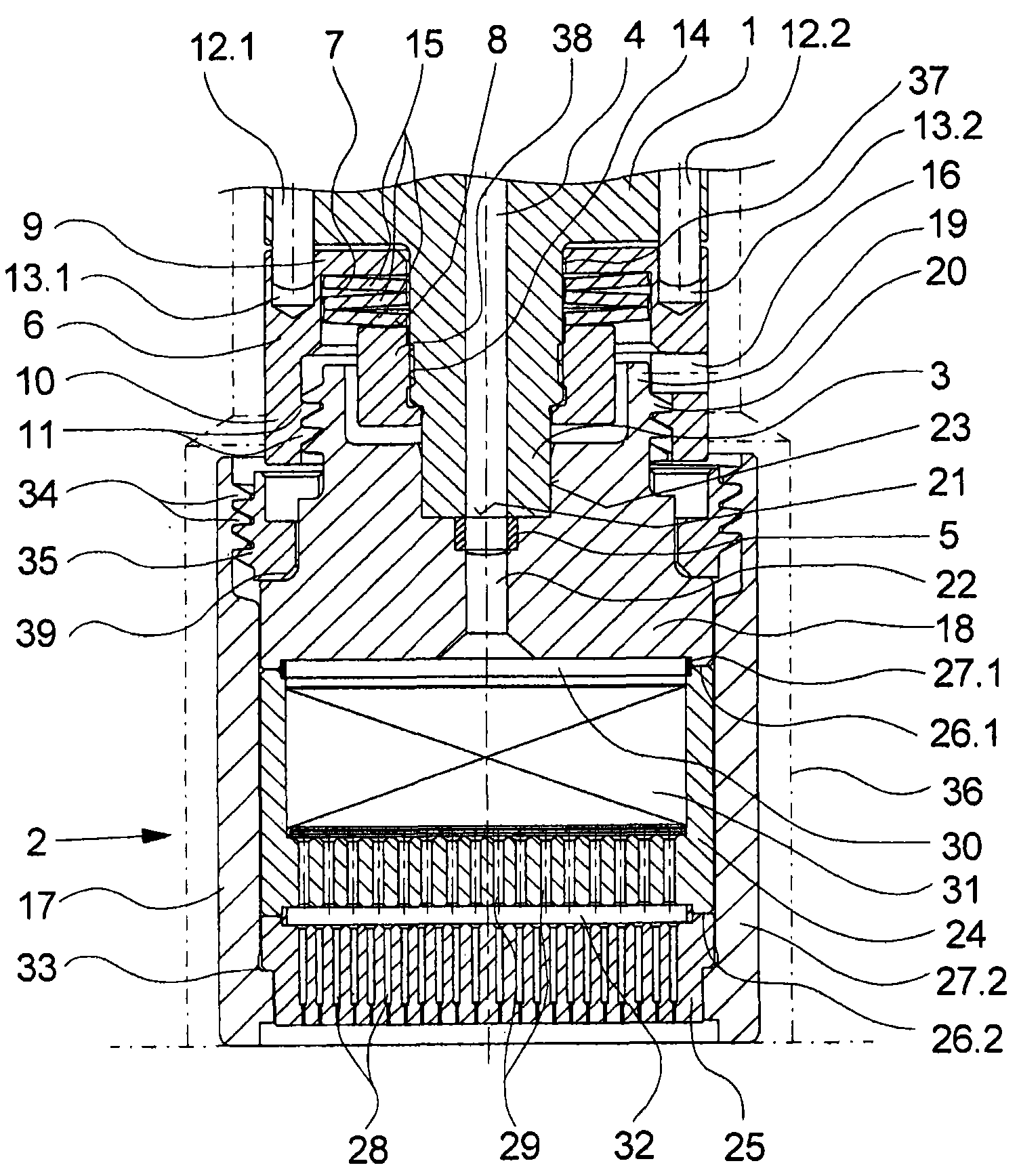
[0030] exist figure 1 A first embodiment of a spinning device according to the invention is shown in . This exemplary embodiment comprises a nozzle holder 1 with a cylindrically protruding melt connection 3 on its underside. In the present exemplary embodiment, the nozzle holder 1 is only partially shown. Typically, a plurality of nozzle holders are arranged side by side in a spinning apparatus to receive a plurality of spinning nozzle assemblies. For this purpose, the nozzle holder has nozzle receiving openings which are preferably dimensioned such that a spinning nozzle assembly held on the nozzle holder 1 is substantially surrounded by the walls of the nozzle holder. The nozzle holder has a heating element (not shown here), so that the spinning nozzle assembly is heated in the nozzle receiving opening via the wall of the nozzle holder 1 . exist figure 1The nozzle receiving opening 36 is indicated by dotted lines in .

[0031] The melt connection 3 on the underside of t...


PUM


Abstract

The present invention relates to a spinning device used for melting a plurality of single filaments.filaments. The spinning device is provided with a nozzle bracket and a detachable spinning nozzle assembly. The spinning nozzle assembly is held to a fusant connector of the nozzle bracket through at least one fusant inlet. For fixing the spinning nozzle assembly, a holding ring which surrounds the fusant connector is provided. The holding ring is connected with the nozzle bracket and is movably held in the axial direction relatively to the fusant connector through the spring component. Hereon, the spinning nozzle assembly and the holding ring are connected so that the fusant inlet is held to the fusant connector under the pre-tightening function caused by the spring component. For realizing enough pre-tightening force, the holding ring has screw thread at a free end, wherein the screw thread cooperates with a corresponding screw thread on the spinning nozzle assembly.

Description

technical field [0001] The invention relates to a spinning device for melt spinning a plurality of monofilaments according to the preamble of claim 1 and to such a spinning device according to the preamble of claim 11 spinning nozzle components. Background technique [0002] In the production of synthetic filaments, a polymer melt must be extruded into a plurality of very fine filaments. For this purpose, the polymer melt is extruded through a plurality of fine capillaries. The capillaries are arranged in a spinneret, which is combined with the distribution plate and the filter element to form a structural unit. Such structural units are also referred to as so-called spinneret assemblies. Such spinneret assemblies are cleaned regularly due to melt deposits deposited on the plates and holes of the spinneret assembly over time. In this context, it is known to detachably fasten spinning nozzle assemblies on nozzle holders, wherein the nozzle holders have melt connections wh...

Claims


Application Information

Patent Timeline
IPC IPC(8): D01D4/00D01D4/02
CPCD01D4/02
Inventor D·维莫尔U·恩德斯H·迈泽D·舒尔茨W·威布肯D·科尔纳H·R·鲍姆
Owner OERLIKON TEXTILE GMBH & CO KG
Why Eureka
Try Eureka