Circular knitting machine

A technology of circular knitting machine and knitting machine, applied in the directions of knitting, weft knitting, textile and paper making, etc., can solve the problems of needle damage, mechanical loss, time-consuming maintenance, etc.

Active Publication Date: 2010-02-03
STAEUBLI ITAL
View PDF8 Cites 2 Cited by
  • Summary
  • Abstract
  • Description
  • Claims
  • Application Information

AI Technical Summary

Problems solved by technology

Likewise, when transferring knitting loops from one cylinder to another, misalignment or out-of-synchronization can lead to needle damage
Such damage to circular knitting machines often has serious consequences, as the damage can spread to many needles and mechanical parts, requiring very expensive and time-consuming repairs
[0004] In order to prevent any risk of misalignment or desynchro

Method used


Image

  • Circular knitting machine

Examples


Example Embodiment

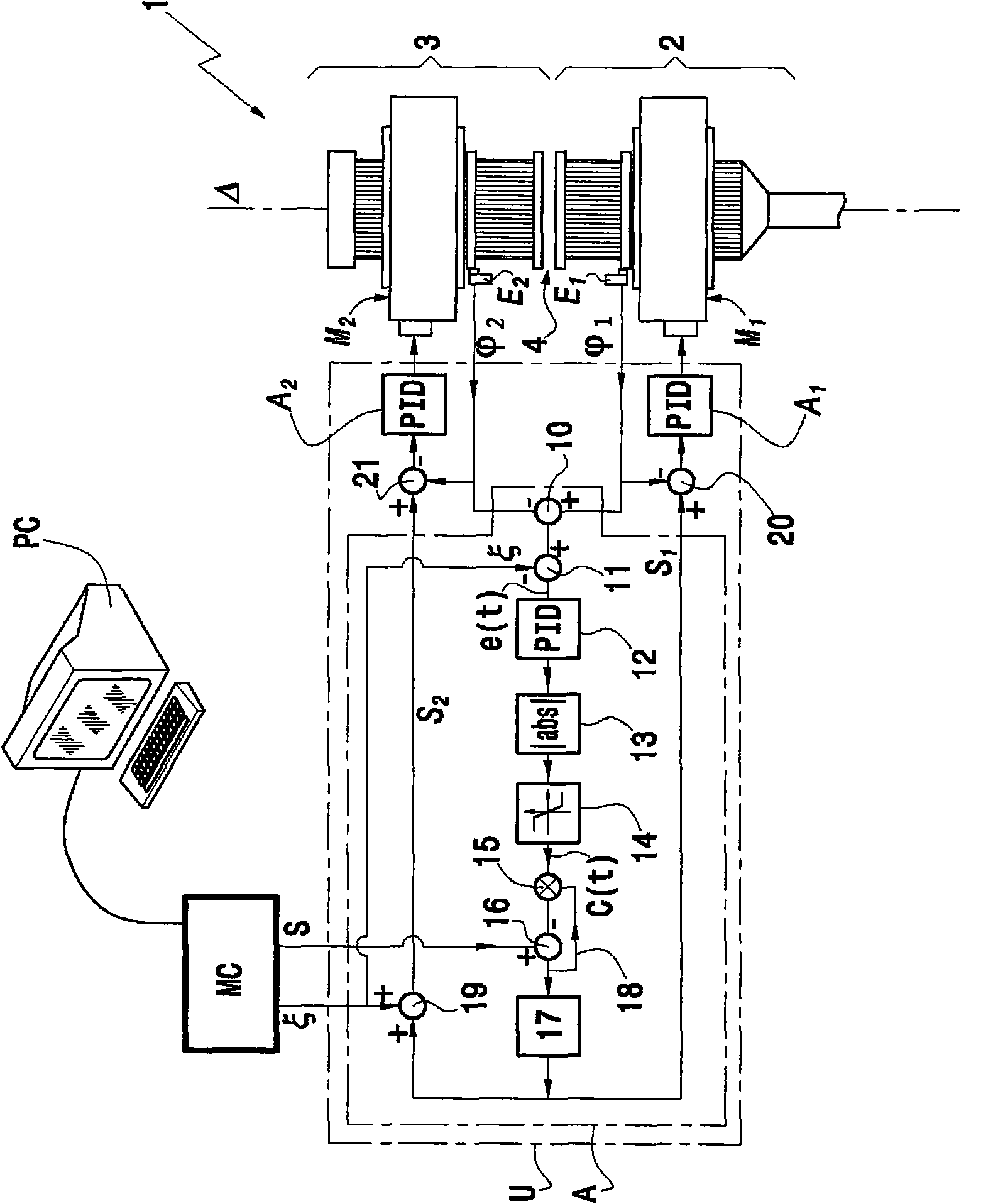
[0045] Such as figure 1 The circular knitting machine according to the invention shown and indicated generally by the reference numeral 1 comprises a lower cylinder 2 rotating about a vertical axis Δ. Above the lower cylinder 2, the circular knitting machine 1 comprises a coaxial upper counterpart 3 which also rotates about a vertical axis Δ. In the example shown, the circular knitting machine is a double-cylinder knitting machine, and the mating part 3 is also a needle cylinder with needles (not shown) extending at its lower part, and the needles of the lower needle cylinder 2 are located thereunder. The upper part of the syringe extends. The needles of the lower needle cylinder 2 and the upper needle cylinder 3 cooperate with each other to form a knitting loop in the middle part 4, thereby knitting hosiery or other items, for example. According to a technique well known to those skilled in the art, the needles are arranged in the grooves of the upper and lower needle cylind...


PUM


Abstract

The present invention relates to a circular knitting machine and a method for controlling the rotation of a lower cylinder (2) and an upper coaxial counter part (3) of the circular knitting machine, wherein the method comprises the steps of: driving with a first electric motor (M1) the rotation of the lower cylinder (2), driving with a second electric motor (M2) the rotation of the upper counterpart (3), detecting the angular position (phi1) of the lower cylinder (3), detecting the angular position (phi1) of the upper counter part, controlling electronically the rotation of the first and second motors by determining of a first set-point (S1) for the first motor and a second set-point (S2) for the second motor according to: the main set-point provided by the knitting program, the difference between the detected position phi1 of the lower cylinder and the detected position phi2 of the upper counter part, and eventually the desired phase shift zeta between the lower cylinder and the upper counter part provided by the knitting program. Knitting machine implements such method.

Description

technical field [0001] The invention relates to circular knitting (knitting) machines with one or two cylinders. The invention relates more particularly to the control of the rotation of a cylinder and its counterpart, which is the other cylinder for a double cylinder knitting machine or the dial for a single cylinder knitting machine. plate). Background technique [0002] A double cylinder knitting machine generally consists of two vertical coaxial cylinders facing head-to-head with a small gap between them. Both barrels have the same number of grooves, each adapted to hold a moving needle. Typically, each needle has a hook at one end that forms a knitted loop (stitch). The two syringes, respectively the lower and the upper syringe, rotate with their needles, retaining grooves aligned. Depending on the desired knitting pattern, some hooks are fed (yarn) by the yarn guide near the edge of the cylinders, approximately in the center of the gap between the cylinders. From ...

Claims


Application Information

Patent Timeline
IPC IPC(8): D04B15/16D04B15/99
CPCD04B15/94D04B15/99
Inventor N·贝洛米M·马蒂亚
Owner STAEUBLI ITAL
Why Eureka
Try Eureka