Stereoscopic image display and method for producing the same

A technology for stereoscopic images and image display, which can be used in stereoscopic systems, image communication, stereophotography, etc., and can solve problems such as reducing stereoscopic effects and reducing image clarity.

Inactive Publication Date: 2010-02-03
SONY CORP
View PDF6 Cites 19 Cited by
  • Summary
  • Abstract
  • Description
  • Claims
  • Application Information

AI Technical Summary

Problems solved by technology

Crosstalk is a phenomenon that reduces the sharpness of the image percei...

Method used


Image

  • Stereoscopic image display and method for producing the same
  • Stereoscopic image display and method for producing the same
  • Stereoscopic image display and method for producing the same

Examples


Embodiment Construction

[0027] Embodiments of the present invention will now be described. The description will proceed in the following order:

[0028] 1. Exemplary Structures of Stereoscopic Image Displays (First Exemplary Structure and Second Exemplary Structure)

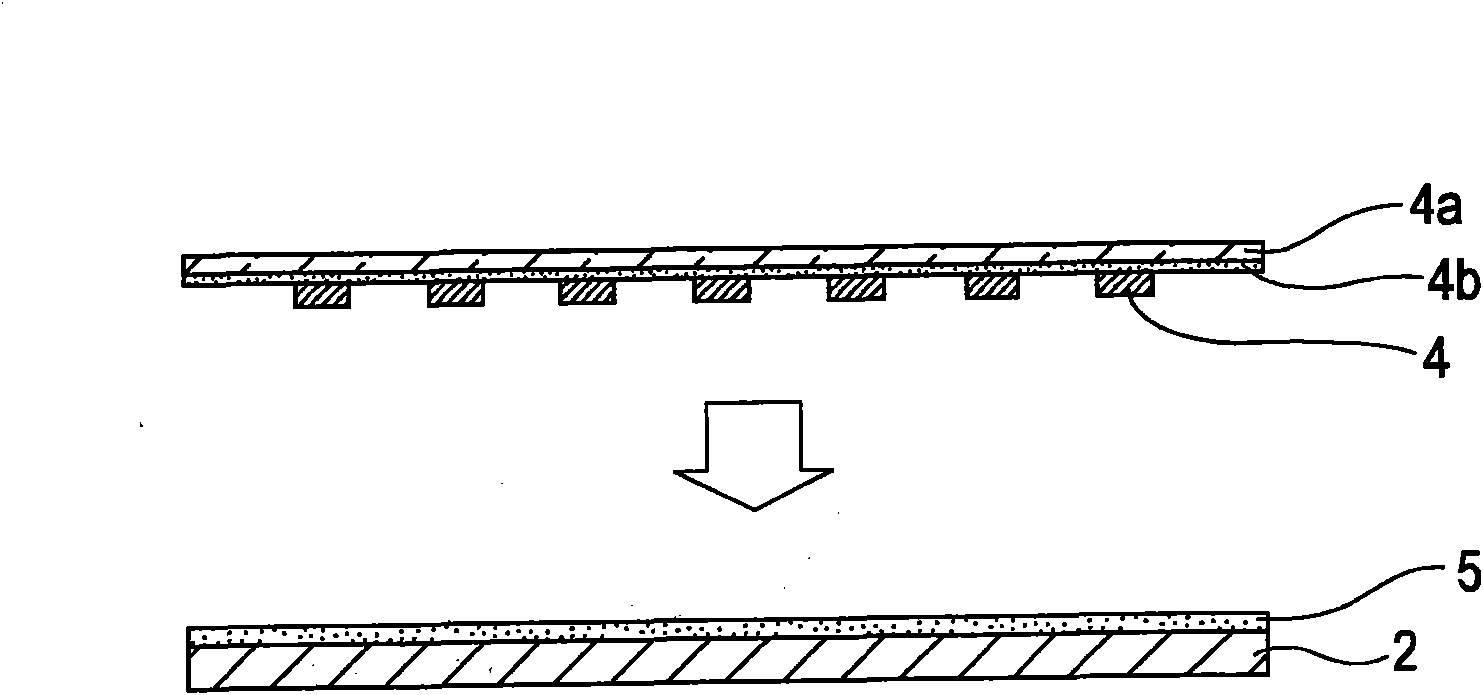
[0029] 2. Method for manufacturing a stereoscopic image display (annealing step, light-shielding layer setting step, positioning step and bonding step)

[0030] 3. Advantages of the embodiment

[0031] 1. Exemplary Structure of a Stereoscopic Image Display

[0032] First, an exemplary structure of a stereoscopic image display according to this embodiment will be described.

[0033] 1-1. The first exemplary structure

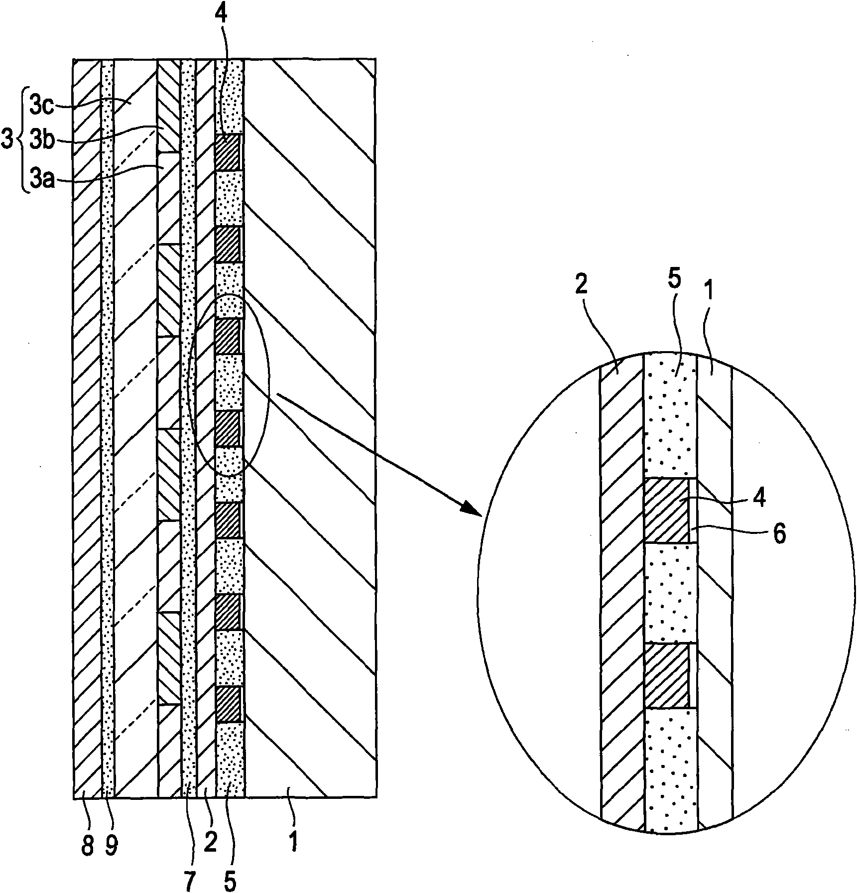
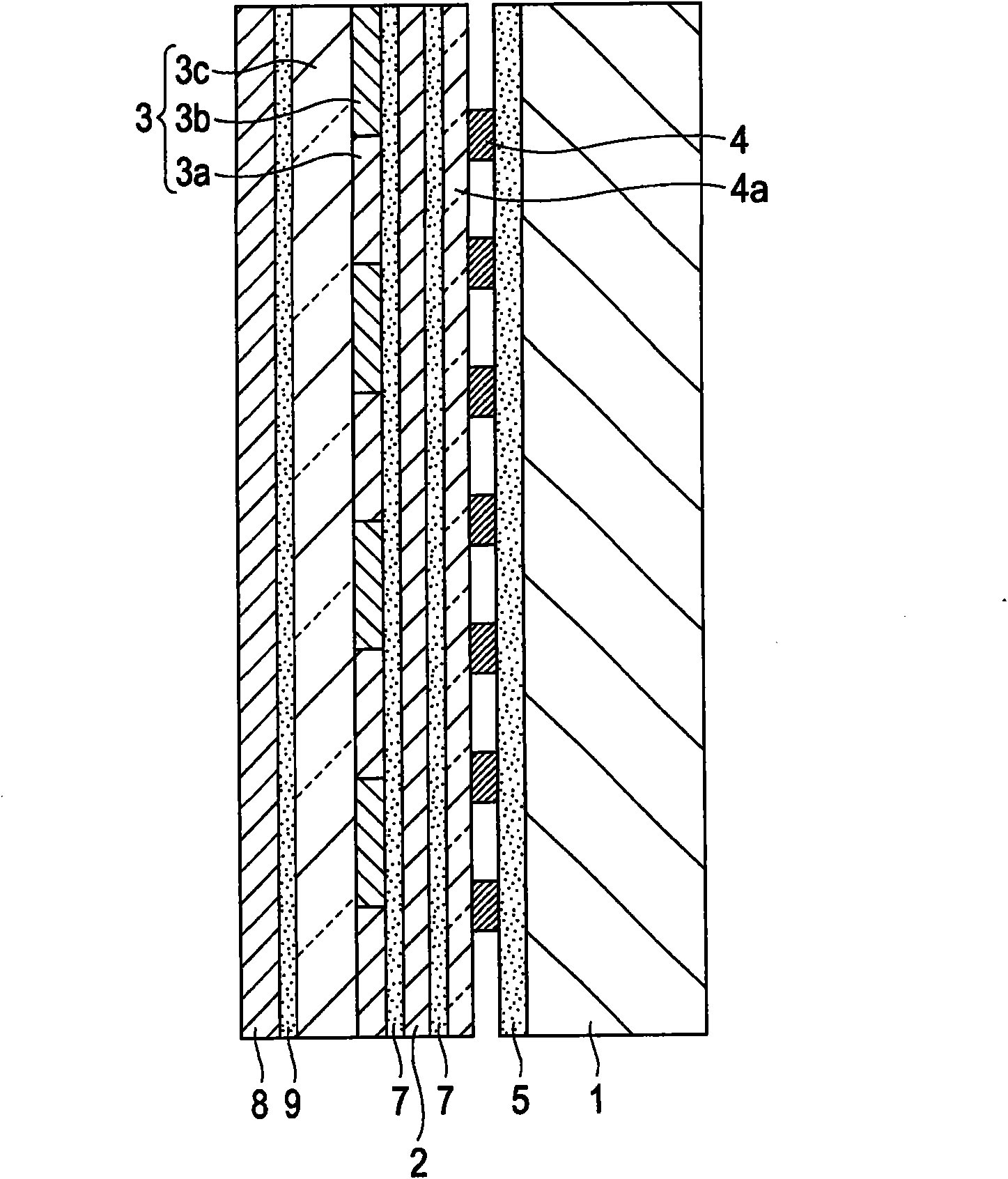
[0034] figure 1 is a schematic diagram of a first exemplary structure of the stereoscopic image display according to this embodiment.

[0035] The shown stereoscopic image display includes an image display panel 1, a polarizer 2, a phase difference element 3, a light shielding layer 4, a first adhesive layer 5, an a...


PUM

PropertyMeasurementUnit
Thicknessaaaaaaaaaa
Hardnessaaaaaaaaaa

Abstract

The present invention provides a stereoscopic image display and a method for producing the same. A stereoscopic image display includes an image display panel that displays right-eye images and left-eye images in a regularly mixed pattern in a plane; a retarder disposed on an image output side of the image display panel and including right-eye-image display portions, corresponding to the right-eyeimages, and left-eye-image display portions, corresponding to the left-eye images, that cause polarization so that the right-eye images and the left-eye images have different polarization states; a polarizer disposed between the image display panel and the retarder; and a light-shielding layer disposed between the image display panel and the polarizer so as to correspond to regions including boundaries between the right-eye-image display portions and the left-eye-image display portions of the retarder.

Description

technical field [0001] The present invention relates to a stereoscopic image display that displays a stereoscopic image using an image for a right eye and an image for a left eye, and a method of manufacturing the same. Background technique [0002] Figure 14 An example of a stereoscopic image display that displays a stereoscopic image is shown (for example, see Japanese Unexamined Patent Application Publication No. 2002-196281 (Patent Document 1)). The shown stereoscopic image display includes an image display panel 51 such as a liquid crystal panel and a retarder 52 provided on its image output side, and is configured so that a viewer can view a display output through polarizing glasses 53 . More specifically, the image display panel 51 displays, for example, the right-eye image R and the left-eye image L in a pattern that is regularly mixed in-plane so that the right-eye image R and the left-eye image L alternate on a horizontal line. The phase difference element 52 inc...

Claims


Application Information

Patent Timeline
IPC IPC(8): G03B35/26G02B27/26G02F1/13H04N13/00G02B30/25
Inventor 阿部比吕宙大野宏饶村英夫柄泽穰司堀江修冈田正道左方笃小林孝之须藤隆信
Owner SONY CORP
Why Eureka
Try Eureka